

 English
 中文简体
中文简体 عربى
عربىWorm Gear Motor Market Developments and User InsightsWorm Gear Motor Overview and User Feedback
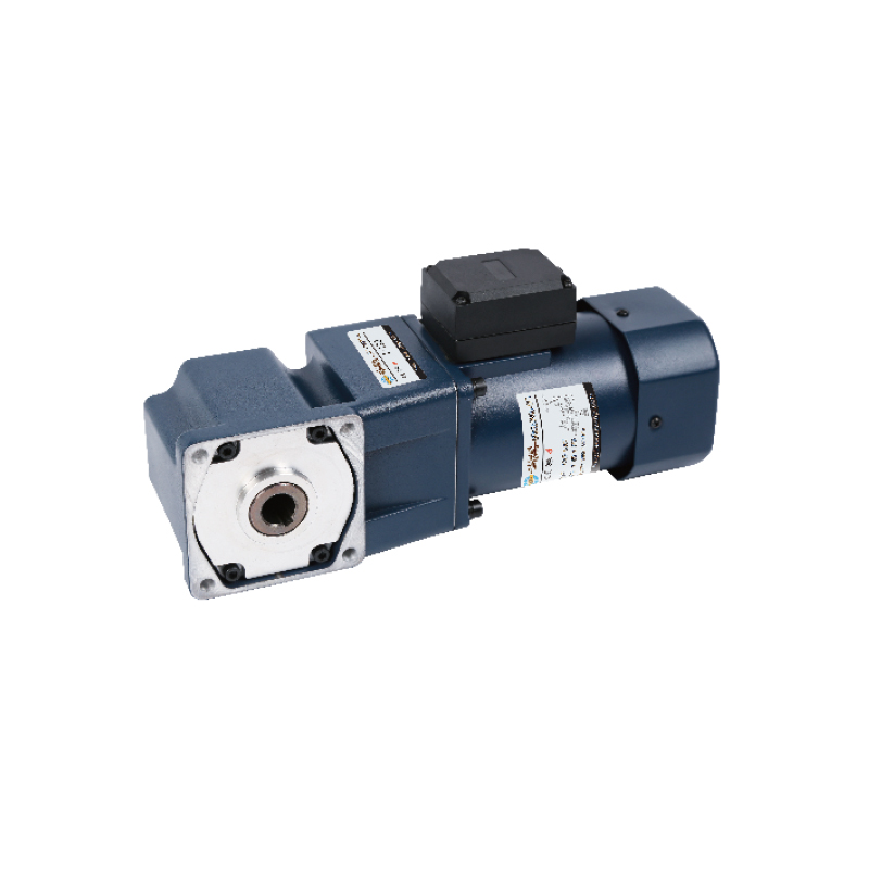
The Worm Gear Motor is widely recognized for its ability to generate high torque in compact applications. It combines a worm screw and a worm wheel, producing a large gear reduction ratio in a small space. This mechanism allows the motor to provide strong holding force, making it ideal for lifting systems, conveyors, and automated equipment that require stability at low speeds.
However, real-world users frequently express both appreciation and concern. Many praise its self-locking property that prevents back-driving when power is cut, while others mention control board failures and alignment challenges. Engineers often ask: “Why does my driver board burn out when connected to a worm gear motor?” Such questions reflect a growing need to understand both the mechanical and electrical characteristics of these systems.
Why Do Driver Boards Often Fail When Using a Worm Gear Motor?
Driver board damage is one of the most common issues discussed among users. The root cause often lies in the high stall current of a worm gear motor. Because the motor is designed for torque multiplication, it can draw two to three times the rated current during heavy loads or startup. If the motor controller or power supply is undersized, voltage spikes and heat can quickly destroy sensitive components.
Engineers recommend allowing at least a 50% current margin when selecting drivers for worm gear systems. The mechanical design of the worm gear—featuring sliding rather than rolling contact—also generates higher friction and temperature rise, which can further affect performance if not properly managed.
Worm Gear Motor Efficiency and Torque Comparison
Compared to spur or planetary gear motors, the worm type offers excellent torque output but reduced efficiency.
Typical torque and efficiency data include:
- Reduction ratio range: 10:1 to 100:1 or more.
- Output torque: from 1 N·m in small DC models up to over 300 N·m in industrial AC units.
- Mechanical efficiency: 60–80%, depending on materials, lubrication, and load.
- Noise level: generally below 60 dB when properly lubricated.
While efficiency is lower than that of spur or helical gear motors (which often exceed 90%), the worm design provides a self-locking effect that prevents reverse motion. This feature is highly valued in hoisting, lift tables, and position-holding systems, where stability outweighs energy loss. Engineers frequently debate whether the trade-off between efficiency and torque is acceptable for their specific applications, leading to broader design diversity across industries.
Common Installation and Maintenance Issues
Users often report mechanical challenges related to mounting, alignment, and lubrication. If the worm gear and wheel are not correctly aligned, the system may suffer from uneven wear, vibration, or shaft bending. Excessive backlash can also occur, especially under repetitive reversing operations. Properly machined housings, rigid bearing supports, and regular lubrication intervals are essential for reliable operation.
Lubrication quality directly affects temperature rise and efficiency. Bronze worm wheels require appropriate lubricants to minimize friction, while hardened steel worms must be checked for surface scoring after long-term use. In continuous-duty systems, even a 5 °C increase in housing temperature can shorten lubricant life by nearly half, emphasizing the importance of preventive maintenance.
Tips for Selecting Reliable Worm Gear Motors
Gear Ratio vs. Speed: Higher ratios deliver more torque but lower speed; balance this according to your load requirements.
Material Selection: Hardened steel worms and bronze wheels offer good durability; aluminum housings provide lightweight structure but lower thermal resistance.
Thermal Management: Closed housings retain heat; adding cooling fins or heat sinks can stabilize operation.
Backlash and Precision: For motion systems requiring accuracy, preloaded bearings and fine machining are essential.
These considerations allow engineers to optimize service life, reduce downtime, and maintain consistent performance across industrial, robotic, and automation environments.
Conclusion
The Worm Gear Motor remains a trusted solution for achieving high torque and self-locking performance in compact machinery. User discussions reveal that its greatest strengths—holding power and stability—are balanced by challenges in heat managemenselection, accurate installation, and proper lubrication, many of these issues can be minimized.
Related Products
-

-

Cat:Right-Angle
The Micro and Special Electronic Motor is designed for compact drive systems requiring reliable performance in limited installation spaces. Its small ...
See Details -

Cat:Right-Angle
The SX Type Junction Box is designed for safe and reliable electrical connection and cable management in motor and industrial equipment systems. Featu...
See Details -
 Gear Motor")
Cat:CH
Small AC Gearmotors are designed for compact power transmission with stable torque output and efficient performance. These Fractional HP Gearmotors ar...
See Details


 Gear Motor")
 Gear Motor")
Looking For Business Opportunity?
Request for a call today
![]()
Zhanpeng Machinery sincerely cooperates with people at home and
abroad to create common development and achieve win-win
results!
Contact Us
-
 sales@razhanpeng.com
-
 +86 13335770176
-
 No. 2807, Huaming Road, Ruian City, Wenzhou City,Zhejiang Province,China
Quick Links
Message


Copyright 2024 Ruian Zhanpeng Machinery Co., Ltd.
Gear Motor Factory


Contact Us