


 English
 中文简体
中文简体 عربى
عربى
Why Industrial Dc Gear Motor Is Used in Daily Automation Tools
Automation has gradually become part of many working environments. Equipment that once depended on continuous manual operation now completes repeated movement with the help of drive systems. Packaging equipment, material handling devices, adjustable platforms, and many small mechanical assemblies all rely on controlled motion instead of simple rotation. Stable movement allows machines to complete the same task again and again while reducing unnecessary adjustment during normal operation.
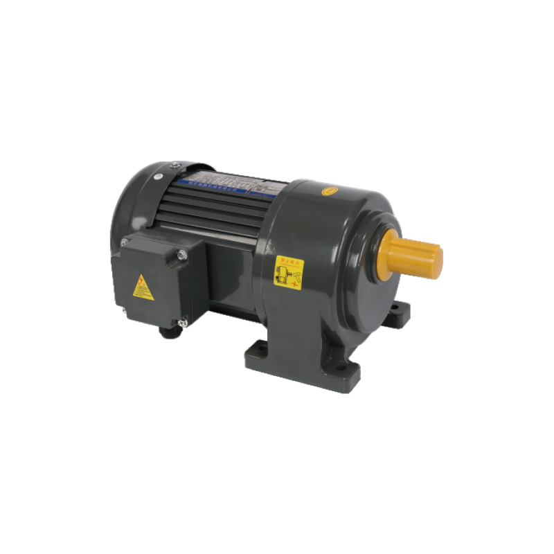
An Industrial DC Gear Motor is often selected for equipment that requires controlled speed together with practical output force. Rather than allowing the motor shaft to rotate freely at high speed, the gear section changes how power is delivered to the connected mechanism. Movement becomes slower, more controlled, and better suited to equipment that performs repeated actions.
Many automation tools also contain belts, wheels, guide rails, chains, or screw mechanisms. Those parts do not always need rapid rotation. In many situations, smooth and steady movement matters more than speed alone. Because of that, a geared motor often becomes part of the overall mechanical design.
Different automation tools place different demands on a drive system. Some need continuous movement for long periods. Others move only a short distance before stopping and starting again. Choosing a suitable drive depends on how the equipment actually works rather than following one general solution.
Why Do Daily Automation Tools Require Controlled Motion
Machines perform many kinds of movement during ordinary operation. Some lift objects. Some push products from one position to another. Others rotate, open, close, feed materials, or adjust working height.
Every movement requires control. Motion that is too fast may reduce positioning accuracy. Motion that is too slow may reduce operating efficiency. A balanced speed allows different mechanical parts to work together more naturally.
Consider a simple conveyor. Products should move forward at a steady pace so that each item reaches the next position in an orderly way. A door mechanism also follows the same principle. Opening too quickly or stopping suddenly may create unnecessary stress on moving parts. Smooth movement usually helps different components operate together more comfortably.
Controlled motion also supports repeated operation.
Common examples include:
- moving a platform between fixed positions
- opening and closing protective covers
- feeding materials into working areas
- adjusting small lifting mechanisms
- positioning components before the next operation
Although equipment designs vary, each relies on movement that follows a planned pattern instead of random speed changes.
One section creates rotational power. The other changes how that rotation reaches the equipment through a gear mechanism.
Without gears, a motor normally rotates at a higher speed than many machines actually require. Gears reduce output speed while allowing movement to become more suitable for mechanical work.
Instead of thinking only about rotation, it is easier to think about how the movement is used.
For example:
- A lifting platform moves steadily instead of rapidly.
- A conveyor advances products at a controlled pace.
- An adjustable bracket changes position smoothly.
- A feeding mechanism moves materials step by step.
In each situation, the equipment benefits from movement that matches its actual task.
Because gears and the motor work together, one compact unit can provide controlled output for many different mechanisms. Designers often choose gear ratios according to the type of movement required rather than applying identical output to every machine.
How Does An Industrial DC Gear Motor Support Automation Equipment
Many automation systems repeat the same action throughout normal operation. Consistency becomes more valuable than sudden bursts of speed because equipment often works alongside sensors, guides, rollers, and mechanical stops.
An Industrial DC Gear Motor supports that type of work by providing steady rotational output that can be transferred through different mechanical structures.
Movement may pass through:
- chain drives
- belt systems
- screw mechanisms
- roller assemblies
- gear transmissions
Each structure changes how motion reaches the working component, yet all begin with controlled rotation from the motor.
Repeated operating cycles also place continuous demands on moving parts. Smooth acceleration and steady movement often allow connected components to work together with less unnecessary vibration.
- Another advantage comes from flexibility during equipment design.
- One machine may require slow movement over a longer distance.
- Another may need short repeated movement with frequent stopping.
- Another may rotate continuously throughout daily operation.
Different gear arrangements allow similar motor technology to support many different types of equipment.
What Makes Industrial DC Gear Motor Different From Standard DC Motors
Although both motor types create rotational movement, their practical use often differs because the output characteristics are not the same.
A standard motor usually provides direct rotational speed from the motor shaft.
As a result, equipment receives movement that is generally easier to control during practical operation.
| Comparison Area | Standard DC Motor | Industrial DC Gear Motor |
|---|---|---|
| Output movement | Direct shaft rotation | Gear-reduced rotation |
| Speed | Higher rotational speed | Lower controlled speed |
| Output force | Direct motor output | Increased through gearing |
| Equipment use | Simple rotating devices | Automated mechanical systems |
| Motion style | Continuous rotation | Controlled mechanical movement |
Difference in structure also changes how equipment behaves during daily work.
A direct motor may suit applications where high rotational speed is useful.
A geared motor often fits machines that need measured movement instead of rapid spinning.
Selecting between the two usually depends on how the mechanical system moves rather than how the motor itself appears.
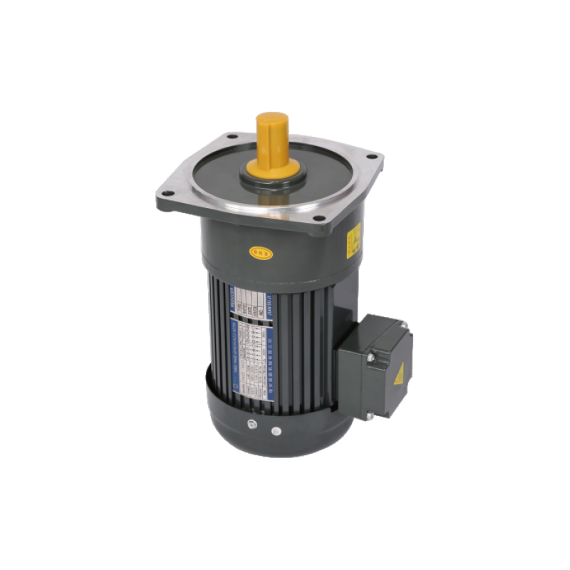
Where Is An Industrial DC Gear Motor Commonly Used
Automation equipment appears in many working environments, even when people do not immediately notice it. Small movement systems often perform repeated tasks quietly in the background. Although machines may look different from one another, many require controlled rotation that matches a specific movement instead of running at the same speed all the time.
An Industrial DC Gear Motor is often chosen because its output can match different mechanical arrangements.
Material handling equipment is one example. Boxes, containers, or components usually move through a planned path. Rolling too quickly may affect the next working step, while movement that is too slow may interrupt the overall process. Controlled output helps different parts continue operating in sequence.
Small conveyor equipment follows a similar idea. Rollers need steady rotation so that products continue moving without sudden changes in speed. A stable drive also allows sensors and positioning devices to work under more predictable conditions.
Automatic doors and movable panels also rely on measured motion. Opening and closing should happen at a comfortable pace, allowing the moving parts to work together smoothly. Gear reduction helps support that type of movement.
Packaging equipment often contains several independent actions. One section may move products forward, another may position materials, while another completes a repeated mechanical cycle. Each movement has its own rhythm, making controlled rotation more practical than unrestricted speed.
Other common examples include:
- adjustable work platforms
- sorting equipment
- feeding mechanisms
- movable inspection devices
- compact lifting assemblies
Although each application is different, movement usually follows the same idea. Speed should match the task rather than remain unchanged under every condition.
What Should Be Considered When Choosing An Industrial DC Gear Motor
Selecting a drive unit usually begins with understanding how the machine moves. Looking only at motor size rarely provides enough information. Movement distance, operating pattern, installation space, and mechanical structure all influence the choice.
One practical question concerns output speed. Some equipment performs better with slow and steady movement, while other machines require quicker rotation. Matching motor output with actual working conditions often creates smoother operation.
Output force is another consideration. Moving a light guide rail is different from driving a lifting mechanism or rotating a loaded roller. Mechanical resistance changes from one application to another, so the drive should suit the work being performed.
Several points are commonly reviewed before selecting equipment.
- Expected movement speed.
- Required output force.
- Available installation space.
- Working environment.
- Daily operating pattern.
- Ease of future maintenance.
Mechanical connection also deserves attention. Couplings, belts, gears, chains, or screw mechanisms should work comfortably with the motor output. A balanced combination often supports stable movement over long periods of use.
Choosing according to the complete mechanical system usually provides a clearer direction than considering the motor alone.
How Does Regular Maintenance Support Daily Operation
Even a well-designed drive system benefits from routine inspection. Small checks completed during normal maintenance often help owners notice changes before they affect machine operation.
An Industrial DC Gear Motor usually operates alongside several connected components. Looking at the complete drive system instead of only the motor often provides a better understanding of operating condition.
Routine inspection may include:
- checking mounting bolts
- observing electrical connections
- removing dust around the motor
- listening for unusual sounds
- watching whether movement remains smooth
Visual inspection is also useful. Changes around cables, fasteners, or surrounding mechanical parts sometimes become visible before they affect daily operation.
Cleaning surrounding areas is another simple habit. Dust, loose material, or accumulated debris may gradually influence moving components. Keeping the area clean supports regular inspection and makes future maintenance easier.
Maintenance records can also help. Noting inspection dates and small observations allows maintenance teams to compare operating conditions over time. Small changes are often easier to identify when previous inspections have been documented.
Why Does Matching Motor Output With Equipment Matter
Every automation tool is designed to perform a specific movement. Some lift, some rotate, while others push or position materials. A motor that matches one machine may not suit another because movement requirements are different.
An Industrial DC Gear Motor is selected according to how motion will be used after leaving the output shaft. A conveyor, for example, benefits from steady rotation over a long period. A positioning mechanism may move only a short distance before stopping. An adjustable platform may require smooth movement during lifting and lowering.
Matching output to the task helps connected parts operate together more naturally.
Questions often considered during equipment planning include:
- Does the machine move continuously or intermittently?
- Does movement need careful positioning?
- Will mechanical resistance change during operation?
- Does the equipment require frequent starting and stopping?
- Can the installation space accommodate the drive system comfortably?
Looking at movement instead of motor appearance often results in a more suitable choice.
Automation equipment depends on cooperation between many mechanical parts. Motors, gears, rollers, guides, chains, belts, and supporting structures all contribute to the same movement. When one section operates differently from the others, overall performance can become less consistent.
Controlled rotation helps each component work within its intended range. Parts move in sequence, positioning becomes easier to repeat, and everyday operation follows a more predictable pattern.
An Industrial DC Gear Motor plays an important role because it combines rotational power with gear reduction inside one compact assembly. Rather than supplying high-speed rotation directly, it provides movement that can be adapted to practical mechanical work.
As automation continues to appear in more production equipment and service machinery, controlled motion remains an important part of equipment design. Selecting a drive according to actual operating conditions, maintaining it through regular inspection, and matching its output with the complete mechanical system all contribute to stable day-to-day operation without relying on unnecessary complexity.
Related Products
-

-
Cat:Right-Angle
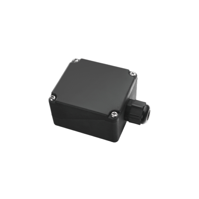
The SX Type Junction Box is designed for safe and reliable electrical connection and cable management in motor and industrial equipment systems. Featu...
See Details -
Cat:CH
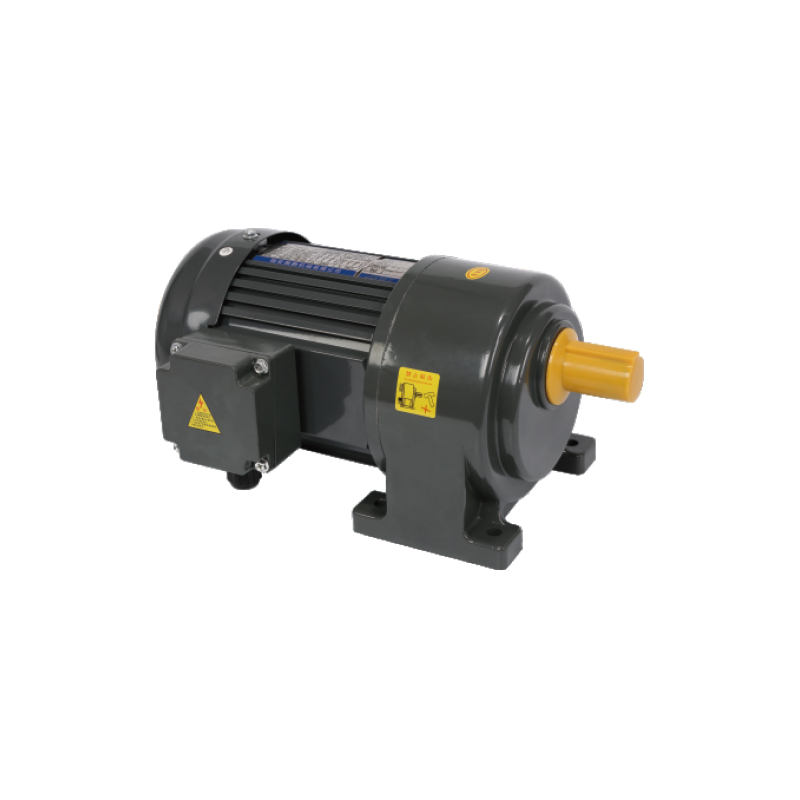
AC Brake Gear Motor is designed with an integrated braking system to ensure precise stopping and stable control during operation. This AC Gear Motor W...
See Details -
Cat:CH
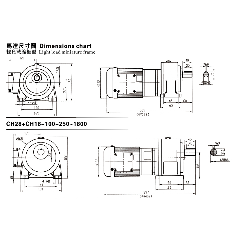
This CH, CV Dimensions Chart showcases a premium Gear Reduced Electric Motor series engineered for light-load, miniature frame applications. The chart...
See Details -
Cat:CH
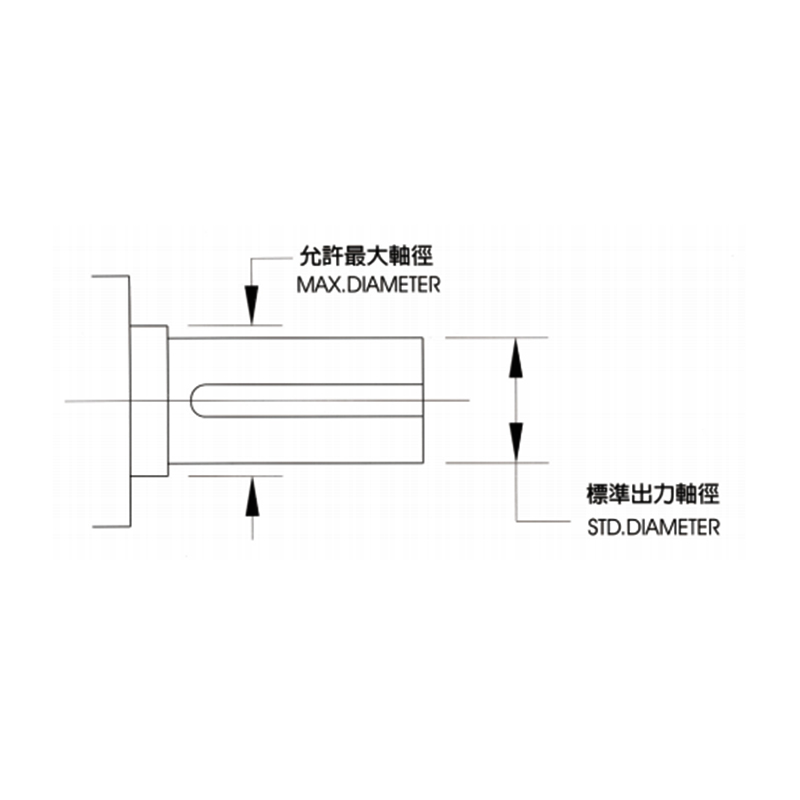
The CH, CV Available Max Output Shaft Diameter provides detailed reference data for selecting suitable shaft dimensions in transmission systems. It he...
See Details -
Cat:CH
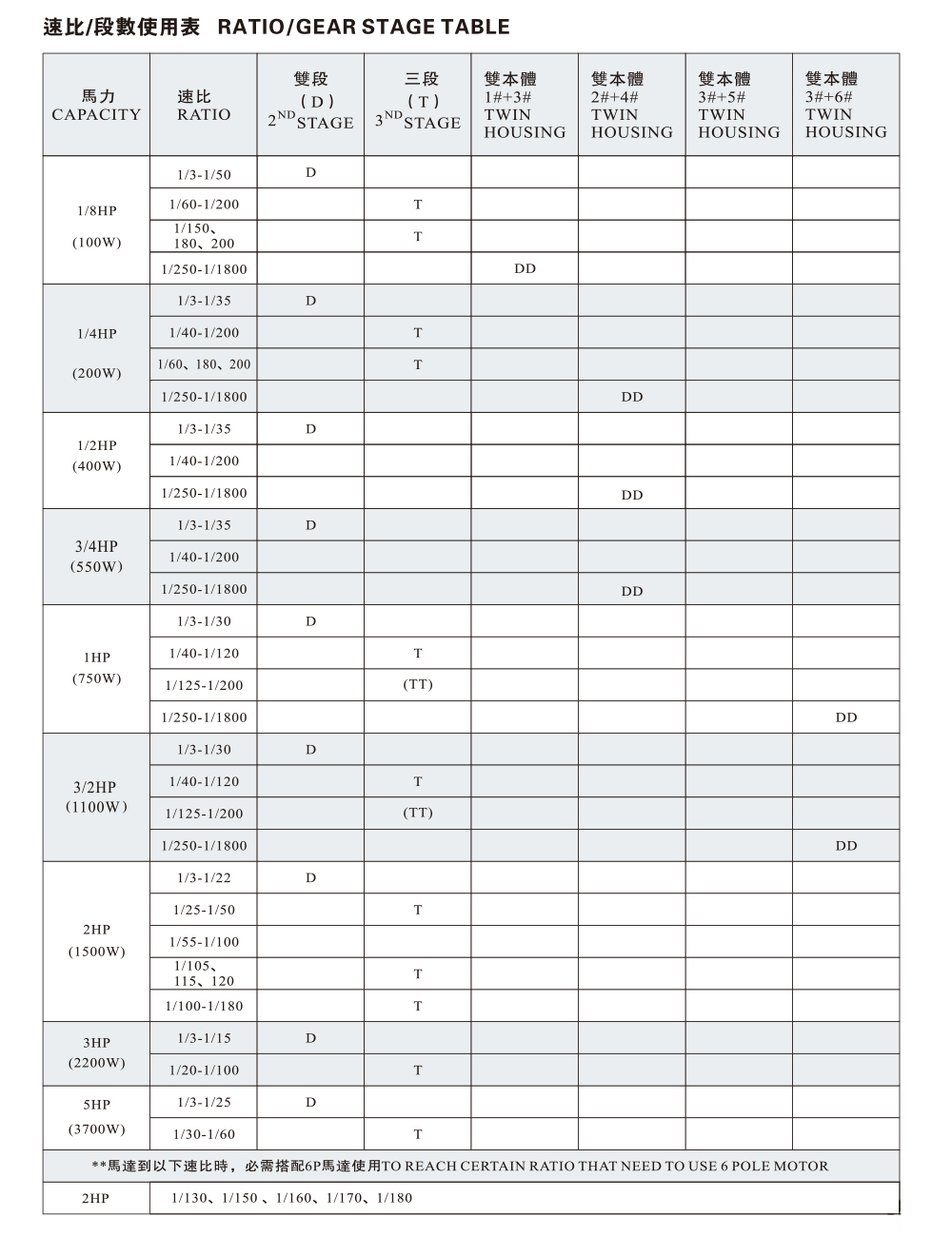
The CH, CV Ratio / Gear Stage Table provides standardized transmission ratio and gear stage information to support equipment selection and system desi...
See Details
Looking For Business Opportunity?
Request for a call today

Zhanpeng Machinery sincerely cooperates with people at home and
abroad to create common development and achieve win-win
results!
Contact Us
-
 sales@razhanpeng.com
-
 +86 13335770176
-
 No. 2807, Huaming Road, Ruian City, Wenzhou City,Zhejiang Province,China
Quick Links
Message


Copyright 2024 Ruian Zhanpeng Machinery Co., Ltd.
Gear Motor Factory


Contact Us