


 English
 中文简体
中文简体 عربى
عربى
How a Heavy Duty Gear Motor Supports Material Handling Systems
Material handling systems are built around movement. Goods need to travel from one position to another, often along a fixed route where speed, direction, and timing all affect how smoothly work can continue. A conveyor may carry boxes across a production area, while another machine may move heavier loads upward or push materials into a different position.
Simply producing rotation is not enough for such tasks. An ordinary motor can rotate at a speed that does not suit the movement required by a conveyor or lifting mechanism. Fast rotation at the motor shaft may need to be changed before it reaches the part that actually moves the load.
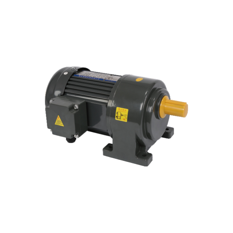
A gear motor provides a connection between motor rotation and practical machine movement. Gears reduce rotational speed while changing how much turning force reaches the output shaft. As a result, a Heavy Duty Gear Motor can be used where the driven equipment needs controlled movement rather than rapid free rotation.
Material handling also involves changing conditions. A load may remain still before movement begins, travel at a steady pace for a period, then stop when it reaches another station. Each stage places a different demand on the drive system.
A useful way to view the drive is through three basic actions:
- Starting a stationary load
- Moving a load along a planned route
- Stopping or changing the movement
Gear reduction helps connect motor behavior with those practical actions. Rather than treating a gear motor as an isolated power source, its role can be considered as part of the movement system that carries material through a working area.
How Gear Reduction Changes the Way Materials Move
A motor naturally produces rotary movement. Material handling equipment, however, often needs a slower and more controlled movement at its working end. Gear reduction creates a change between motor rotation and output shaft movement, allowing the driven part to rotate at a pace suited to the machine.
Consider a conveyor carrying materials along a fixed path. Rapid movement at the conveyor surface may cause goods to arrive at a work position before the next operation is ready. A slower output can provide a more manageable pace, allowing movement to match the surrounding equipment.
Gear reduction also changes the turning force available at the output. Lower output speed can be accompanied by greater turning force, giving the drive a more suitable relationship with a load that needs to be moved.
Speed and turning force therefore cannot be considered separately. A change in one affects how the machine behaves at the point where movement takes place.
| Material Handling Task | Movement Requirement | Gear Motor Role |
|---|---|---|
| Conveyor movement | Steady travel | Adjust output speed for the conveyor |
| Load pushing | Controlled forward motion | Provide suitable turning force |
| Lifting movement | Slower directional travel | Adapt motor rotation to the lifting mechanism |
| Position transfer | Measured movement | Match output movement with machine timing |
Gear reduction does not simply make a motor rotate more slowly. It changes how motor energy reaches the driven mechanism. For material handling, that difference can determine whether a machine moves a load smoothly or struggles when movement begins.
How a Gear Motor Handles the Start of a Load
Starting a load creates a different situation from keeping an already moving load in motion. At rest, the material and the connected machine parts need to begin moving together. Resistance from the equipment, contact surfaces, and load weight can all affect the starting process.
A conveyor carrying a heavy group of goods provides a clear example. Before movement begins, rollers and other moving parts are stationary along with the load. Once the drive starts, every connected part needs to respond to the motor output.
A suitable gear arrangement helps provide controlled turning force at the output shaft. Such control allows the drive to work with the mechanical structure rather than sending rapid rotation directly into the handling mechanism.
Starting behavior also depends on how the load is placed. A spread‑out load may interact with the conveyor differently from a concentrated load. A heavy object positioned near one section can create a different starting condition from several lighter objects distributed along the route.
For that reason, motor selection needs to consider the actual movement rather than load weight alone.
Important conditions include:
- Whether the load starts from a complete stop
- How the load is distributed
- Whether movement begins horizontally or vertically
- How much resistance comes from the driven mechanism
- Whether starts occur occasionally or repeatedly
A Heavy Duty Gear Motor is therefore not simply chosen because a machine carries heavy materials. Its output needs to correspond with how movement begins and how the connected mechanism responds during that initial stage.
Why Continuous Material Movement Requires Stable Output
Once a load begins moving, another requirement appears: maintaining a steady movement through the handling path. A conveyor does not simply need enough force to start. Output also needs to remain suitable while goods continue traveling.
Changes in output movement can affect how materials are spaced along a conveyor. Goods moving at an uneven pace may approach another machine too quickly, leave larger gaps, or fail to remain in the intended position.
Stable output also matters when several mechanical parts work together. A motor may drive a roller, which then moves a belt or another carrying surface. Each part depends on the previous part to transfer movement consistently.
Mechanical connections deserve attention here. Loose or poorly aligned connections can interrupt otherwise steady motion, creating unnecessary changes in how the load moves. Gear motor selection and machine structure therefore need to be considered together.
Continuous movement can be viewed through a few simple factors:
- Output speed remains suitable for the handling task.
- Turning force remains appropriate as the load changes.
- Mechanical connections transfer movement without unnecessary movement.
- The driven part follows the intended direction.
A Heavy Duty Gear Motor supports continuous handling by converting motor rotation into a form that suits the equipment. Its contribution is not limited to producing force. Controlled output helps establish a predictable relationship between motor movement and material movement.
How Load Changes Influence Gear Motor Performance
Material handling rarely involves a completely unchanged load from beginning to end. A conveyor may run empty for part of a cycle, carry several small items during another section, and then receive a heavier object. Each condition changes the demand placed on the drive.
Load distribution matters as well. Weight positioned evenly along a moving surface creates a different mechanical condition from weight concentrated in one area. Vertical movement introduces another change because the drive must work against the direction of gravity during lifting.
Friction within the handling equipment can also vary. Rollers, belts, chains, wheels, or other moving parts each create their own resistance. A gear motor therefore works within a larger mechanical system rather than dealing with the material alone.
| Load Condition | Possible Effect on Movement | Design Attention |
|---|---|---|
| Empty equipment | Lower resistance | Avoid unnecessary output force |
| Light distributed load | Moderate demand | Maintain steady movement |
| Concentrated load | Higher local resistance | Consider starting conditions |
| Heavy moving load | Greater drive demand | Match output with machine movement |
| Changing load | Variable operating condition | Allow for different movement states |
Repeated changes in load can also affect the rhythm of a handling process. A drive that works well during an empty cycle may behave differently once material enters the system. Matching output characteristics with the expected range of working conditions helps keep movement more consistent.
Custom Gear Motors become relevant when the load pattern or machine structure does not fit a simple arrangement. Output direction, mounting position, shaft arrangement, and available space can all influence how a drive needs to interact with the handling equipment.
Load, speed, and machine movement are closely connected. Looking at only one factor can give an incomplete picture of the drive requirement. A Heavy Duty Gear Motor needs to be considered according to the actual task performed by the material handling system, especially where movement changes from one operating condition to another.
Where Custom Gear Motors Become Useful
Material handling equipment does not always leave much room for a drive unit. A conveyor may have a narrow frame, a lifting machine may require an offset connection, and a transfer mechanism may need the output shaft to face a particular direction. Such conditions can make the relationship between the motor and the driven part more important than the motor itself.
Custom Gear Motors can be considered when a standard arrangement does not fit the mechanical layout. Customization may involve the mounting position, output shaft direction, connection structure, or overall dimensions. Each change needs to relate to an actual requirement within the handling equipment.
Mounting position is particularly important. A motor placed too close to another moving part may interfere with normal operation or make later adjustment difficult. A unit positioned farther away may require a different connection route. Space around the drive also needs to remain practical for assembly.
Output direction creates another design consideration. A straight shaft arrangement may suit a simple conveyor, while another machine may need the output to reach a mechanism located beside the motor. Changing the relationship between the motor and output can make the drive fit more naturally into the equipment.
Customization therefore starts with the machine layout rather than with appearance. Useful questions during design include:
- Where will the motor be mounted?
- Which direction should the output face?
- How will the output connect with the moving mechanism?
- How much space is available around the drive?
- Which parts need to remain accessible?
A Custom Gear Motors design can help bring the drive and machine structure into a closer mechanical relationship. Such an approach is relevant where the movement path, available space, or connection position differs from a common arrangement.
How Motor And Conveyor Design Need to Work Together
A gear motor cannot be separated completely from the equipment it drives. Motor rotation eventually reaches a conveyor roller, moving surface, lifting part, or another mechanism, so the characteristics of both sides need to fit together.
A conveyor provides a simple example. The drive turns a mechanical part, and that movement is transferred to the carrying surface. A mismatch between output movement and conveyor requirements can affect how material travels along the route.
Connection position also matters. A motor mounted in an unsuitable location may require additional mechanical parts to reach the conveyor. Extra connections can increase the complexity of the arrangement and create more points that need adjustment during installation.
Alignment plays a similar role. When the output shaft and driven part do not sit naturally along the intended path, additional force may appear around the connection. A properly arranged drive allows movement to pass through the machine with fewer unnecessary changes in direction.
Good coordination between motor and conveyor design considers:
- Output direction and driven‑part position.
- Required movement speed.
- Load distribution along the conveyor.
- Available mounting space.
- Connection alignment.
- Access around the drive.
A Heavy Duty Gear Motor should therefore be selected as part of the conveyor structure rather than as an independent component. The motor provides rotational movement, while the surrounding mechanical design determines how that movement becomes useful material movement.
What Makes a Gear Motor Suitable for Heavy Material Handling
A larger load does not automatically mean that a particular gear motor will suit a handling system. Suitability depends on how the load moves, how often movement starts and stops, how the weight is distributed, and how the driven mechanism responds.
Output speed is one consideration. A conveyor carrying materials through a work area may need controlled movement rather than rapid rotation. A lifting mechanism may require another movement pattern because the load travels vertically.
Output turning force also needs to match the machine. Starting a stationary load can place different demands on the drive compared with maintaining movement after the load has already begun traveling.
Mechanical construction has a role as well. A Heavy Duty Gear Motor used in material handling needs to work with the supporting structure, output connection, and driven components. A suitable motor arrangement should not require excessive mechanical adjustment to compensate for an unsuitable installation position.
| Handling Requirement | Drive Consideration | Reason for Attention |
|---|---|---|
| Heavy starting load | Suitable output turning force | Supports initial movement |
| Continuous travel | Controlled output speed | Helps maintain a steady material path |
| Changing load | Appropriate working range | Handles different operating conditions |
| Limited installation space | Suitable mounting arrangement | Keeps the machine layout practical |
| Special movement direction | Suitable output orientation | Connects with the driven mechanism |
Such evaluation keeps attention on the actual handling task. Motor size alone gives limited information about how a drive will behave once connected to a working machine.
How Gear Motor Selection Shapes the Handling Process
A drive choice can influence more than the movement of one mechanical component. Since motor output passes through the machine and eventually reaches the material, changes in speed and turning force can affect how goods travel through the handling process.
For conveyor systems, output speed can influence the pace at which materials move between working areas. A controlled pace can help maintain a consistent flow of goods along a fixed route.
Starting characteristics also affect material positioning. A sudden change in movement may cause loosely placed goods to shift, while a controlled start can allow the carrying surface and material to begin moving together.
Stopping creates another point of interaction. When a conveyor stops, material needs to remain within the intended area rather than continuing forward because of its own movement. Drive behavior therefore becomes part of the physical handling process.
Lifting equipment presents a different relationship. Movement must follow a planned vertical path, and the drive needs to provide suitable output while the load changes position. The connection between motor output and lifting mechanism becomes particularly important because movement direction has a direct effect on the load.
Gear motor selection can consequently influence:
- Movement pace
- Starting behavior
- Material positioning
- Direction of travel
- Interaction between the drive and carrying mechanism
A Heavy Duty Gear Motor is therefore connected to the handling result through the machine structure. Selection should begin with the required movement and then work backward toward the drive arrangement.
Why Drive Design Is Part of Material Handling Design
Material handling equipment is often viewed through its visible moving parts: conveyors, rollers, lifting sections, or transfer mechanisms. Behind each movement sits a drive arrangement that determines how mechanical energy reaches those parts.
A Heavy Duty Gear Motor provides one link in that chain. Motor rotation enters the gear structure, output movement reaches the connected mechanism, and the mechanism transfers that movement to the material. Every stage needs to work with the next stage.
Load conditions add another layer. A machine may begin with no material, receive several items, handle a concentrated load, and then return to an empty state. Drive requirements change along with the working condition.
Custom Gear Motors can address situations where standard mounting or output arrangements do not fit the machine structure. Such designs focus on the relationship between available space, connection position, movement direction, and load handling.
Connection between drive and equipment can therefore be viewed through a simple sequence:
Motor Rotation → Gear Reduction → Output Movement → Mechanical Transfer → Material Movement
Each stage has a practical purpose. Gear reduction changes the form of motor rotation, the output shaft transfers that movement, and the handling mechanism turns rotary motion into useful movement along a planned route.
A well‑planned drive arrangement keeps those relationships in view from the beginning. Instead of treating the motor as a separate part added after the equipment has been designed, the drive can be considered alongside the movement path, load condition, and mechanical layout.
Such an approach gives material handling design a clearer connection between power and movement. Heavy Duty Gear Motor selection then becomes part of deciding how materials should start moving, continue along the route, respond to changing loads, and reach the intended position within the equipment.
Related Products
-

-
Cat:Motor Controller & Accessories
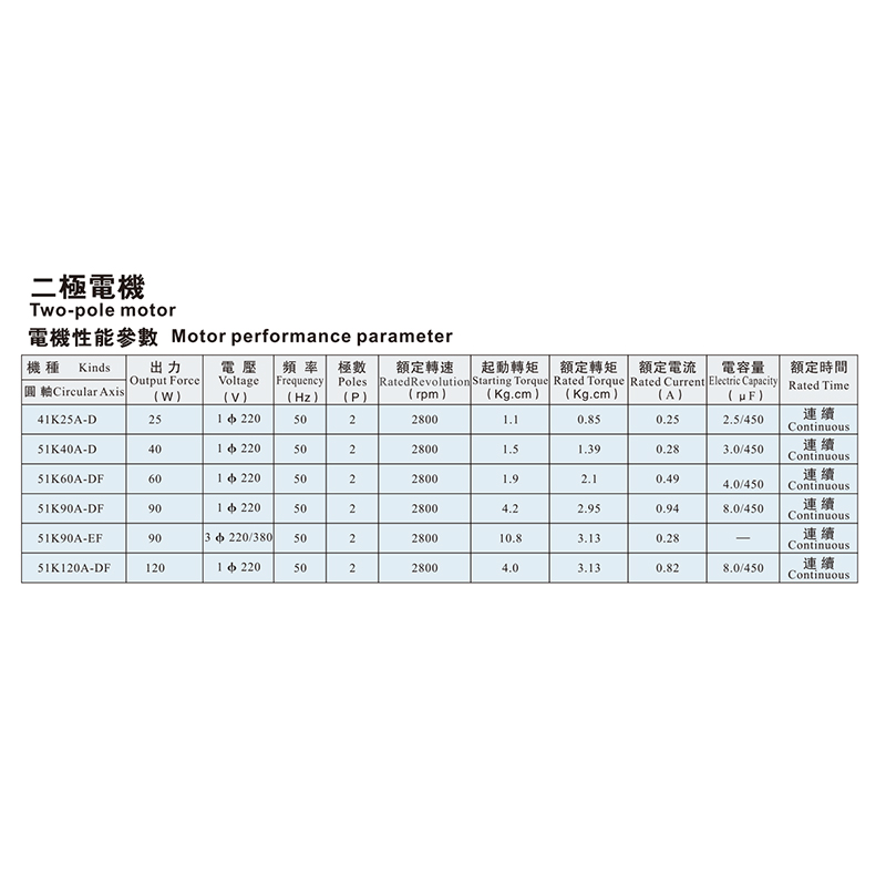
The Two-pole Motor is designed to provide stable and efficient power output for a variety of industrial and automation applications. Its compact struc...
See Details -
Cat:CH
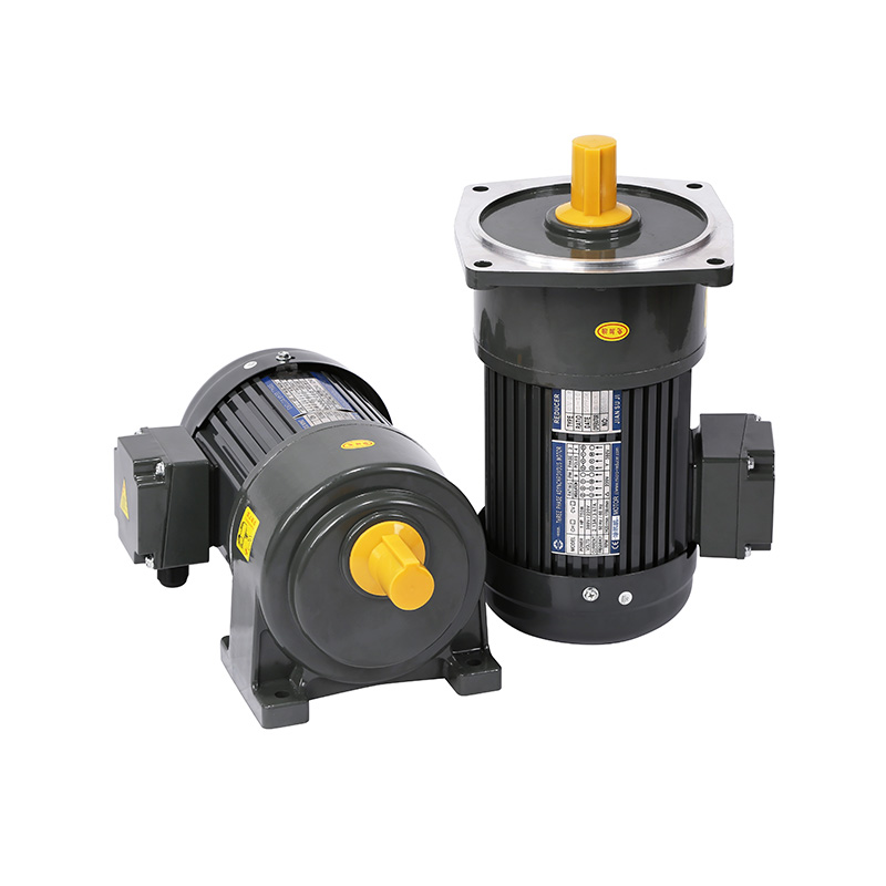
The Mirco and Special Electronic product series is designed for compact electronic equipment and precision transmission applications requiring stable ...
See Details -
Cat:CH
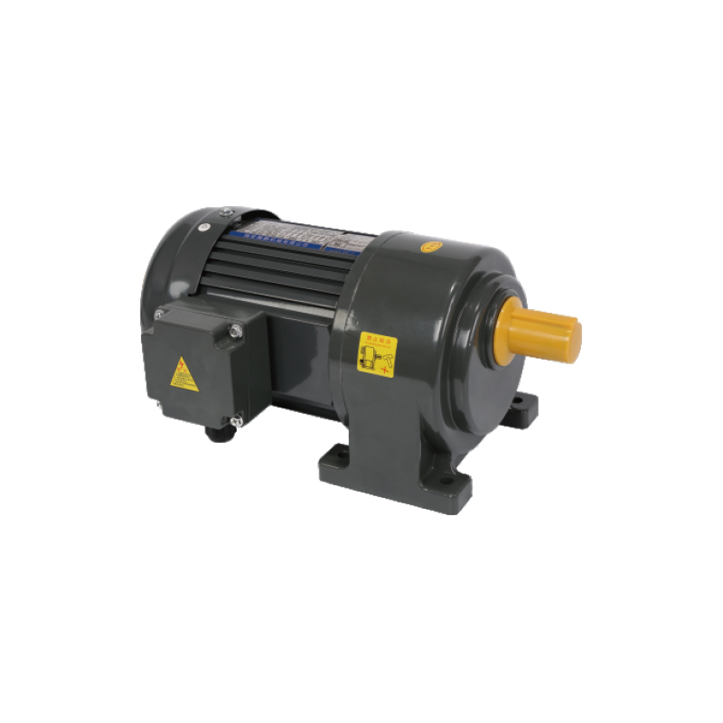
AC Brake Gear Motor is designed with an integrated braking system to ensure precise stopping and stable control during operation. This AC Gear Motor W...
See Details -
Cat:CH
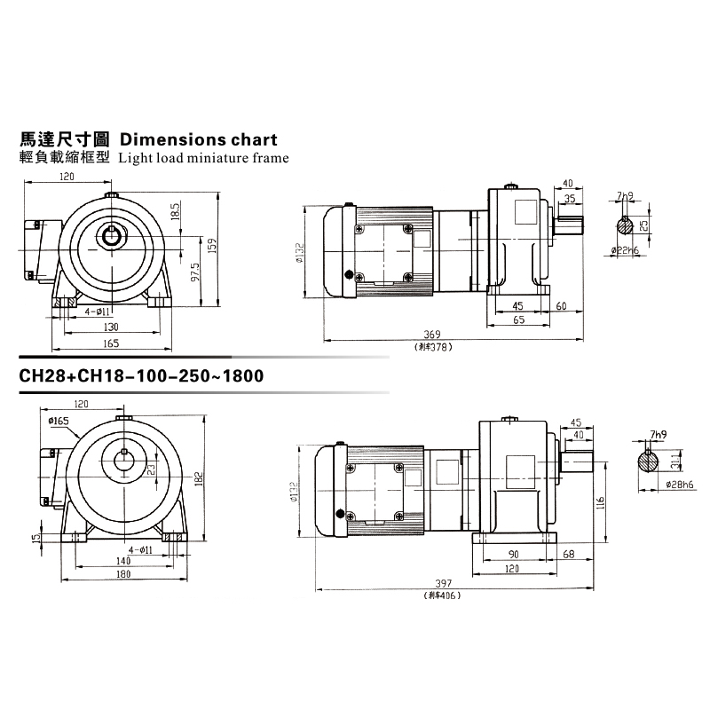
This CH, CV Dimensions Chart showcases a premium Gear Reduced Electric Motor series engineered for light-load, miniature frame applications. The chart...
See Details -
Cat:CH
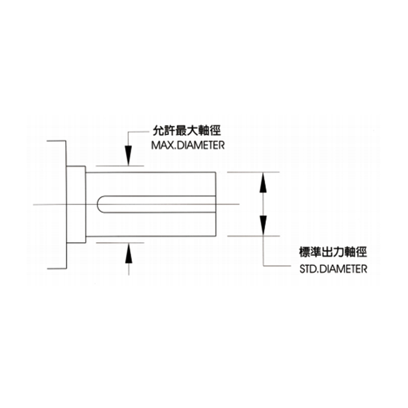
The CH, CV Available Max Output Shaft Diameter provides detailed reference data for selecting suitable shaft dimensions in transmission systems. It he...
See Details
Looking For Business Opportunity?
Request for a call today

Zhanpeng Machinery sincerely cooperates with people at home and
abroad to create common development and achieve win-win
results!
Contact Us
-
 sales@razhanpeng.com
-
 +86 13335770176
-
 No. 2807, Huaming Road, Ruian City, Wenzhou City,Zhejiang Province,China
Quick Links
Message


Copyright 2024 Ruian Zhanpeng Machinery Co., Ltd.
Gear Motor Factory


Contact Us