


 English
 中文简体
中文简体 عربى
عربى
How Do AC Gear Reduction Motors Affect Torque in Everyday Equipment
A motor can spin without necessarily making a machine work well. What matters at the equipment end is how that rotation is delivered. A small mechanism may need to turn slowly while pushing against resistance, while another device may need quicker movement with less turning force. The same motor arrangement cannot suit every working condition.
Torque is the turning force available around a rotating shaft. It affects whether a moving part can start, keep moving, or respond properly when resistance changes. Speed describes how quickly the shaft rotates, so the two properties should not be treated as interchangeable.
Consider a simple rotating mechanism. When there is little resistance, a motor can turn it without much difficulty. Add a heavier moving part, increase friction, or make the mechanism move against another component, and the required turning force changes. A drive that seemed suitable during an unloaded test may behave differently once the equipment is operating normally.
That is one reason an AC Gear Reduction Motor is used in equipment where direct motor rotation does not match the required movement. The motor supplies rotary power, while the gear section changes how that power reaches the output shaft. The output can rotate at a lower speed while providing a higher level of turning force, with some power lost through mechanical resistance in the gear system.
For practical equipment design, torque affects several parts of normal operation:
- Starting: A mechanism needs enough turning force to overcome resistance when it begins moving.
- Continuous movement: Once moving, the required force may change depending on the load and friction.
- Changing loads: Added material or movement through a different position can increase resistance.
- Stopping and restarting: Frequent cycles can place different demands on the drive than steady operation.
- Mechanical wear: An unsuitable load can place additional stress on gears, shafts, and connected components.
The useful question is therefore not simply how much torque a motor can provide. The working conditions determine whether that torque is appropriate.
How Does an AC Gear Reduction Motor Change Motor Output
A motor shaft may rotate considerably faster than the part connected to it needs to move. Directly coupling the two can make the equipment operate too quickly or make movement harder to control. A gear reduction section changes the relationship between the input shaft and output shaft.
The idea is easier to understand through an everyday mechanical example. Imagine using a hand tool to turn a resistant part. A longer handle makes it easier to apply turning force, although the movement at the end of the handle becomes slower. Gears work through a related mechanical principle. They exchange rotational speed for turning force as motion passes from one gear to another.
Inside a reduction unit, the motor drives an input gear. That gear transfers motion to another gear, and the process may continue through the arrangement until the output shaft is reached. A larger driven gear turns more slowly than a smaller driving gear when they engage directly. Changing the gear arrangement therefore changes the speed and torque available at the output.
For equipment designers, the important point is that the output should be judged at the point where the machine actually does its work. Looking only at the motor shaft can give an incomplete picture.
A practical evaluation usually considers:
- Input rotation — how the motor operates before the reduction section.
- Gear arrangement — how the gears alter speed and turning force.
- Output condition — what the final shaft needs to do under the real load.
- Mechanical losses — how friction and other resistance reduce usable power.
The output does not gain unlimited force simply because gears are added. Part of the available energy is consumed as moving parts contact one another. Gear condition, lubrication, alignment, and assembly also affect the amount of power that reaches the output.
The operating feel of the equipment can change as well. A slower output may make a mechanism easier to control, particularly when a sudden movement could affect the position of a connected part. For a small actuator, rotating fixture, or other compact machine, controlled movement can be more useful than rapid shaft rotation.
The motor and reduction section should therefore be considered as one working arrangement. Changing the gear section can change the behavior seen at the equipment end even when the motor itself remains unchanged.
What Happens to Torque During Speed Reduction
When speed is reduced through gears, turning force at the output generally increases. The reason is mechanical rather than electrical. The gear arrangement changes the way rotational power is transferred from the motor to the driven shaft.
A useful comparison is a bicycle moving up a slope. A lower gear allows the rider to turn the pedals more easily against resistance, although the bicycle travels a shorter distance for each pedal rotation. Gear reduction in a motor system follows a related idea: output rotation becomes slower while greater turning force is made available.
Real equipment, however, does not behave like an ideal calculation. Gears rub against one another, shafts rotate within supporting parts, and seals or other mechanical components create resistance. Some of the motor's power is therefore lost before it reaches the output.
The condition of the gear system can also change the result. Poor alignment may cause uneven contact between gear teeth. Insufficient lubrication can increase friction. Wear can alter the way gears engage. None of those factors changes the basic purpose of reduction, yet they can affect how smoothly the available torque reaches the machine.
| Factor | What Changes During Operation | What to Check |
|---|---|---|
| Motor rotation | Provides the input movement | Whether the motor speed suits the reduction arrangement |
| Gear size and arrangement | Changes output speed and turning force | Whether the output matches the working movement |
| Mechanical resistance | Uses part of the available power | Gear condition, lubrication, and shaft movement |
| Equipment load | Changes the torque required at the output | Starting and running resistance under actual conditions |
| Shaft alignment | Can affect smooth power transfer | Whether connected parts remain properly aligned |
Starting conditions deserve particular attention. A machine may require more turning force when stationary because the drive has to overcome initial resistance. Once movement begins, the required force can fall. The difference is easy to miss when a motor is tested without the actual load.
The opposite situation can also occur. A mechanism may start easily and then encounter greater resistance as it moves. A lifting mechanism, rotating fixture, or material‑moving device can behave this way because the mechanical load changes with position.
For that reason, torque should be considered across the working cycle rather than at a single moment. A drive that can turn a mechanism freely does not automatically have enough capacity for the same mechanism under normal operating resistance.
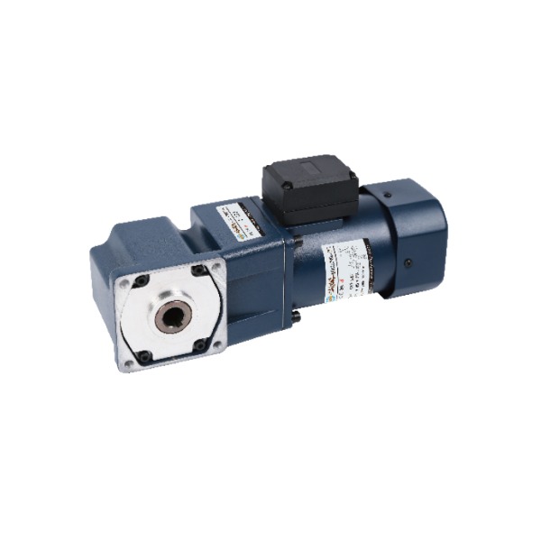
How Load Conditions Affect Everyday Motor Performance
Load is where the difference between a motor running on a test bench and a motor working inside equipment becomes noticeable.
An unloaded shaft may rotate smoothly because there is little resistance. Once connected to gears, rollers, fans, pumps, moving arms, or other mechanical parts, the motor has more work to do. The amount of resistance depends on the weight and movement of the connected parts, friction, the way the load is applied, and whether the machine has to start and stop repeatedly.
Startup deserves separate attention. At rest, a moving mechanism may resist movement more than it does after it has begun rotating. A drive therefore needs suitable torque at the beginning of the cycle, not merely enough force to maintain motion afterward.
Load can also change during operation. Imagine a small conveying mechanism moving empty and then carrying material. The motor may appear comfortable during the empty run, while the loaded section requires more turning force. A similar change can occur in a rotating device when the position of a moving component alters the resistance placed on the shaft.
Some common signs of a poor torque match include:
- movement becoming noticeably slower when a load is applied;
- difficulty starting after the equipment has been idle;
- uneven rotation during changes in load;
- increased mechanical noise or vibration;
- greater heating around the drive during repeated operation.
Such symptoms do not automatically point to the motor as the cause. Gear condition, shaft alignment, lubrication, mechanical friction, and the driven equipment itself can produce similar behavior.
A High Speed Micro Motor can be useful where compact equipment needs rapid motor rotation, while a reduction section changes that rotation before it reaches the working mechanism. The resulting output is governed by the complete drive arrangement rather than by the motor's speed alone.
The same principle applies when considering an AC Gear Reduction Motor. Matching the drive requires attention to the load at startup, the resistance during normal movement, and any changes that occur during the operating cycle. Once those conditions are clear, gear selection and motor characteristics can be considered together instead of treating torque as an isolated specification.
That leads directly to the gear structure itself. The way gears are sized and arranged affects not only output speed, but also how smoothly turning force passes through the drive. Small differences in mechanical contact can become noticeable once the equipment is placed under a real working load.
How Gear Design Influences Torque Transmission
The gear section determines how the motor's rotation is changed before it reaches the equipment. Gear size is one part of the relationship, yet the physical condition of the whole transmission path matters as well. Two drives with a similar reduction arrangement can behave differently when their assembly, lubrication, or shaft alignment is different.
Gear teeth need to engage smoothly as rotation passes from one shaft to another. When contact is uneven, part of the input power is spent overcoming additional resistance. The output may still turn, although movement can become less smooth and mechanical noise may increase.
Shaft alignment is easy to overlook during equipment assembly. A motor and its driven mechanism may appear correctly positioned from the outside while a small alignment problem places extra pressure on the gear set. Over time, such a condition can affect gear surfaces and supporting parts.
Lubrication also has a practical role. Moving gear surfaces create friction, and suitable lubrication helps reduce resistance between contacting parts. The required arrangement depends on the gear construction, operating environment, temperature, and equipment design. Too much attention on the motor alone can therefore miss problems within the transmission section.
Gear design also affects how the output responds to changing loads. When the driven mechanism meets greater resistance, the gear teeth transfer a greater mechanical load. The parts need enough strength and suitable contact conditions to handle that change without causing unnecessary movement between the connected components.
For equipment manufacturers, several details are worth checking together:
- gear dimensions and their relationship within the reduction section;
- shaft alignment during assembly;
- contact between mating gear surfaces;
- lubrication condition during operation;
- support for rotating shafts;
- clearance between moving components.
A compact drive often has limited installation space, so the reduction unit cannot simply be treated as an isolated box attached to the motor. Its dimensions, shaft position, mounting method, and connection with the equipment all affect how torque reaches the working mechanism.
Where High Speed Micro Motor Applications Need Different Torque Control
Small equipment often creates an interesting design problem. The motor may be physically compact while the connected mechanism needs controlled movement rather than rapid rotation. A High Speed Micro Motor can provide fast shaft rotation in a small arrangement, while gearing can change the output before it reaches the working part.
Such a combination can appear in compact household equipment, small automated mechanisms, rotating displays, light material‑handling systems, and other devices where installation space is limited. The actual application varies, yet the design question remains similar: how should motor rotation be converted into useful movement?
A fast motor shaft is not necessarily a problem. It becomes a concern when the connected component cannot work effectively at the same rotational speed. Direct connection may produce movement that is difficult to control or place unnecessary demands on the mechanism.
Reduction can change that behavior. The motor continues to provide the input rotation, while the gear section slows the output and increases available turning force. The equipment can then use the output in a way that better fits its mechanical movement.
Noise and vibration also deserve attention in compact equipment. Small housings can make mechanical sounds easier to notice because there is less space between the drive and surrounding components. Gear contact, mounting condition, shaft alignment, and load changes can all influence the operating sound.
Heat is another practical consideration. Mechanical resistance and electrical operation both produce heat, so the motor and reduction section need a suitable way to release it. A compact housing with little room around the drive may require careful placement to avoid trapping heat around the motor.
The working pattern matters too. A mechanism that runs briefly and then stops has different operating conditions from one that rotates continuously. Repeated starts can also change the demands placed on the motor and gears.
Rather than judging a small drive only by its physical size or shaft speed, designers need to consider the complete movement required by the equipment. The useful output is the part that reaches the working mechanism in a form it can actually use.
How Manufacturing Choices Affect Motor Torque Consistency
The behavior of a motor and gear assembly begins to take shape during manufacturing. A gear may have the intended size on a drawing, yet its actual performance also depends on machining, surface condition, assembly, and the relationship between individual parts.
Shafts need to sit in the intended position so that the gears can engage properly. Small differences in component dimensions can influence contact between moving parts. Assembly workers and production equipment therefore need suitable inspection steps before the completed drive enters testing.
Sealing and lubrication arrangements also need attention where they form part of the reduction section. Contamination around moving components can increase resistance, while unsuitable lubrication may affect movement or create additional operating problems.
Production checks can focus on practical signs rather than relying on a single inspection point. For example, manufacturers may examine whether shafts rotate as expected, whether gears move without unusual resistance, and whether the assembled unit produces abnormal noise during operation.
A typical production process may include checks such as:
- Component inspection — confirming that shafts, gears, housings, and related parts are within the intended assembly range.
- Gear assembly — positioning the transmission parts so their contact remains suitable.
- Motor connection — joining the motor and reduction section while maintaining correct shaft positioning.
- Operational testing — observing rotation, sound, vibration, and output movement.
- Final inspection — checking the completed assembly before it is fitted into equipment.
Consistency matters because the same drive design may be used across many pieces of equipment. A change in gear contact or shaft alignment can alter how torque is delivered, even when the motor itself has not changed.
Manufacturing control is therefore connected with actual equipment behavior. It is not limited to whether a component looks correct. The assembled drive needs to operate as a complete mechanical unit.
How AC Gear Reduction Motor Design Is Adapting to Equipment Needs
Equipment design is moving toward more compact and integrated drive arrangements. As machines become smaller, the motor, reduction section, mounting structure, and driven components often need to fit into a limited space without making maintenance unnecessarily difficult.
An AC Gear Reduction Motor can be adapted to different working requirements by changing the relationship between motor output and the final mechanical movement. A device that needs slow rotation may require a different reduction arrangement from one that needs quicker movement. The load pattern also matters, especially when the equipment starts under resistance.
Material selection is another part of the design process. Motor housings, gears, shafts, and supporting components need to suit their operating environment. Moisture, dust, temperature changes, vibration, and repeated movement can all influence how the drive performs over time.
The connection between the drive and the equipment deserves equal attention. Even a properly designed motor assembly can experience problems when the connected shaft is poorly aligned or the mounting structure allows excessive movement. Good equipment design treats the motor as part of the mechanical system rather than as a separate power source.
Maintenance access can influence the design as well. Components that experience friction or repeated movement need to remain accessible enough for inspection and service where required. A compact structure should not make basic checks unnecessarily difficult.
The development of everyday equipment therefore involves several considerations working together:
- required output speed;
- starting and running load;
- available installation space;
- mechanical resistance;
- operating frequency;
- noise and vibration;
- heat release;
- maintenance requirements.
The role of gearing is to make motor rotation useful for the task at hand. A High Speed Micro Motor may provide the rotational input, while the reduction section changes that input into slower movement with greater turning force at the output. The final performance depends on how well those parts work with the equipment around them.
For that reason, torque should be considered as part of the entire drive path. Motor characteristics, gear construction, load conditions, assembly quality, and installation all influence what eventually happens at the working end of the machine. Looking at those elements together gives equipment designers a clearer way to connect motor rotation with practical movement.
Related Products
-
-
Cat:Right-Angle
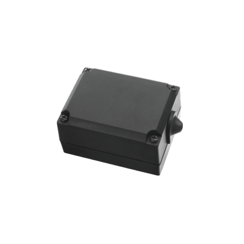
The Power Distribution Junction Box is designed for safe and stable electrical wiring management. With a durable External Junction Box Black structure...
See Details -
Cat:Motor Controller & Accessories
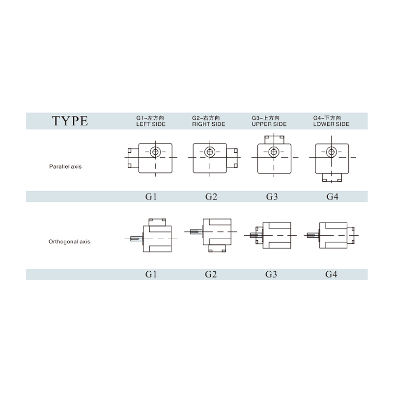
Junction Box Orientation Selected offers flexible installation options to match different equipment layouts and wiring requirements. Available in four...
See Details -
Cat:Motor Controller & Accessories
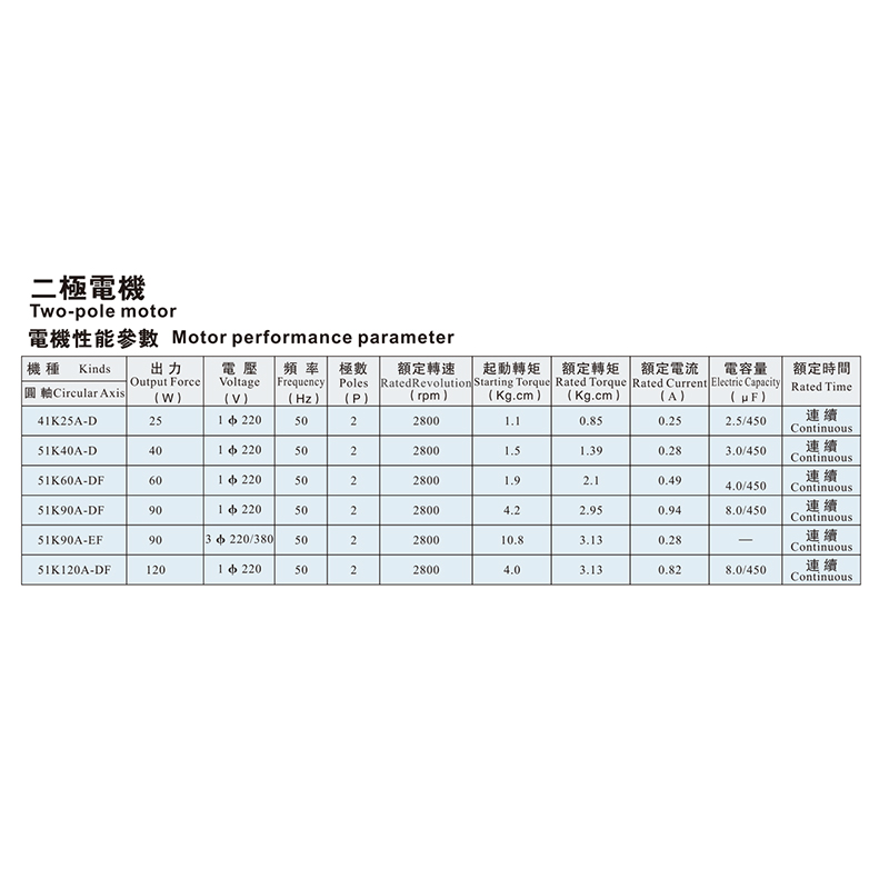
The Two-pole Motor is designed to provide stable and efficient power output for a variety of industrial and automation applications. Its compact struc...
See Details -
Cat:CH
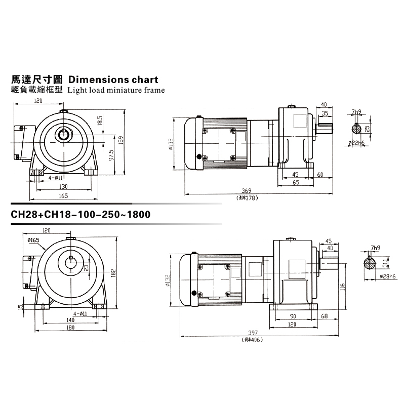
This CH, CV Dimensions Chart showcases a premium Gear Reduced Electric Motor series engineered for light-load, miniature frame applications. The chart...
See Details -
Cat:CH
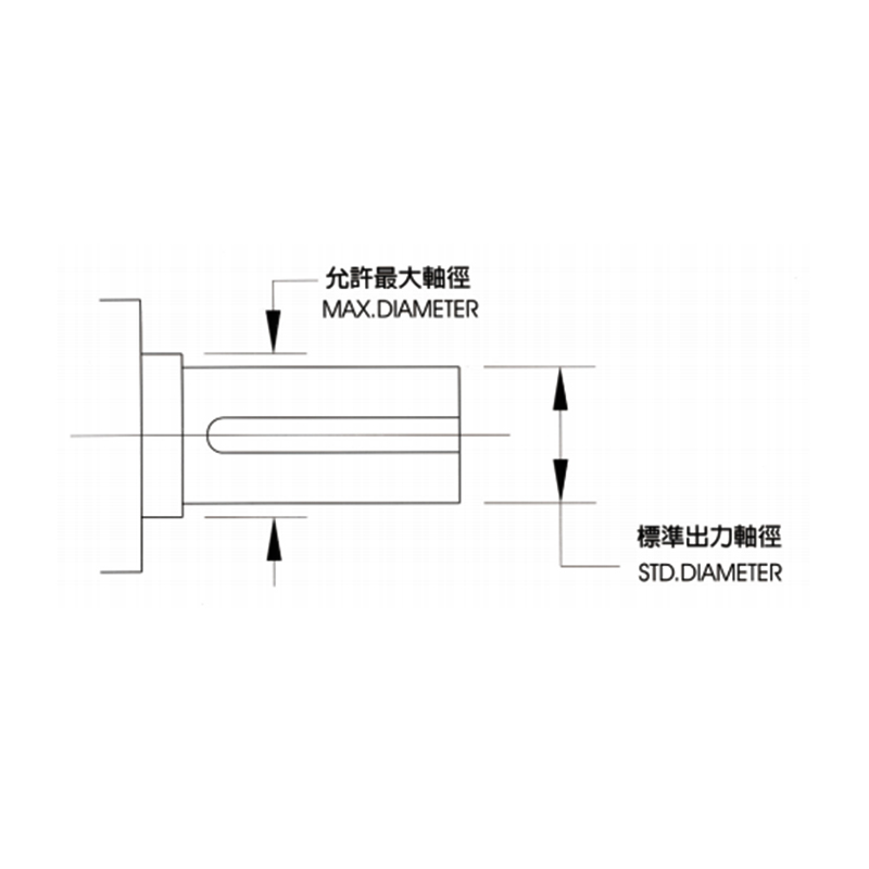
The CH, CV Available Max Output Shaft Diameter provides detailed reference data for selecting suitable shaft dimensions in transmission systems. It he...
See Details -
Cat:CH
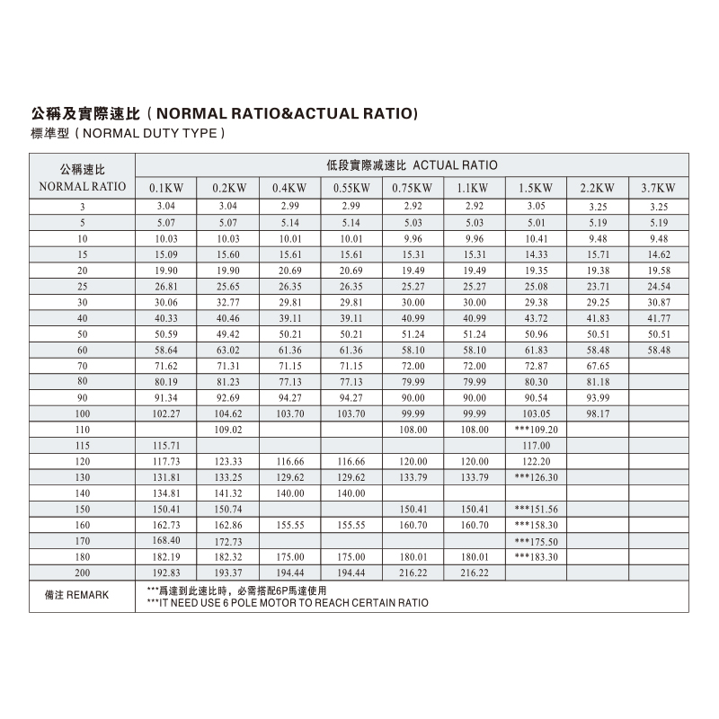
The CH, CV Normal Ratio & Actual Ratio provides accurate reference data for matching transmission requirements and optimizing reducer performance....
See Details -
Cat:CH
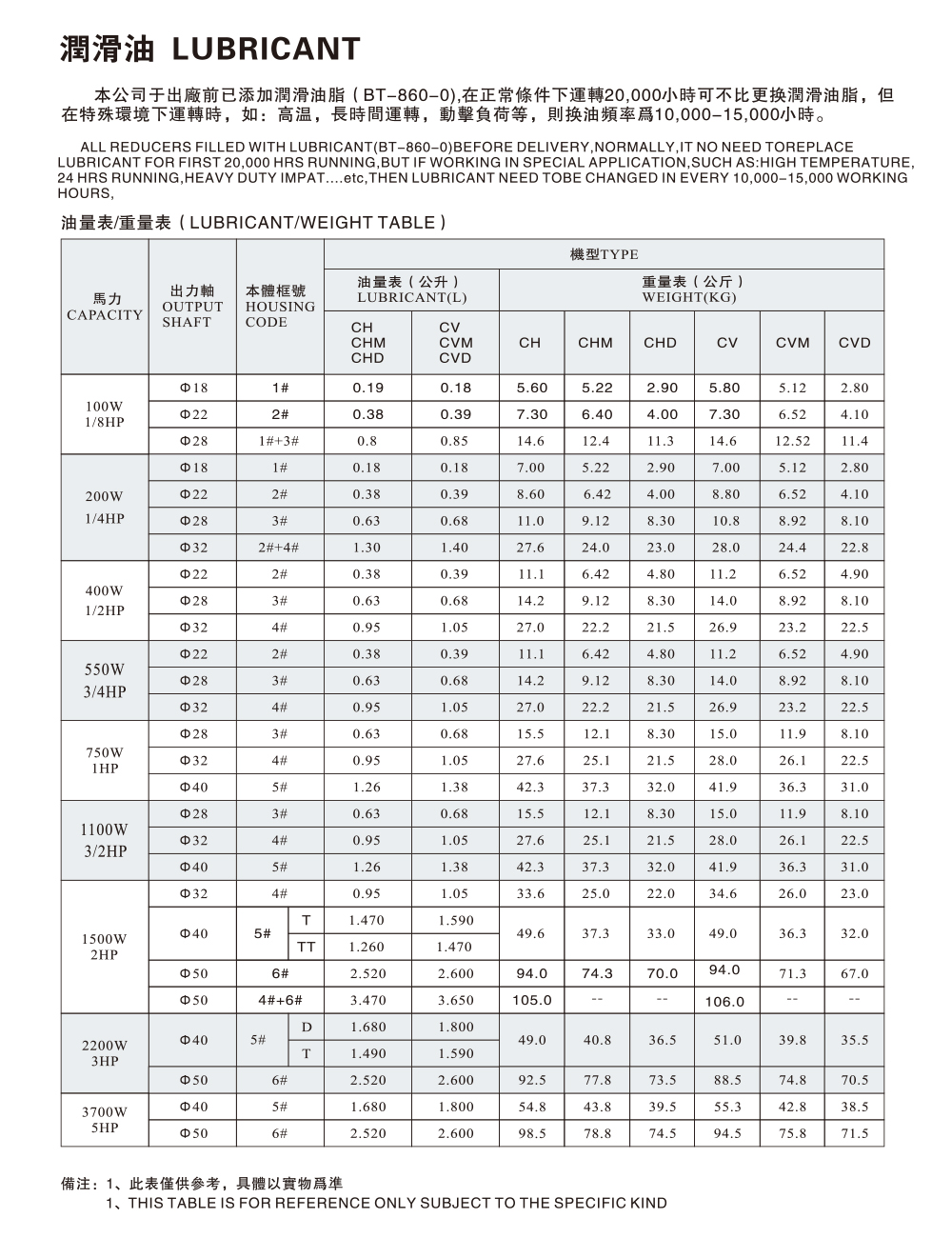
Our company has added lubricating grease (BT-860-0) before leaving the factory. It is not necessary to replace the lubricating grease after 20,000 hou...
See Details -
Cat:CH
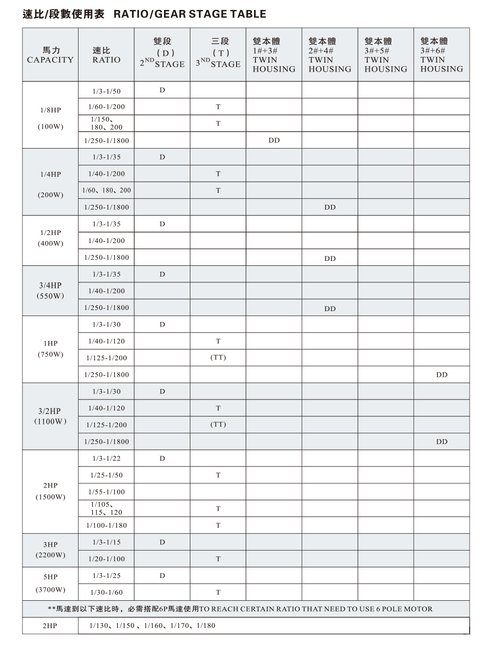
The CH, CV Ratio / Gear Stage Table provides standardized transmission ratio and gear stage information to support equipment selection and system desi...
See Details
Looking For Business Opportunity?
Request for a call today

Zhanpeng Machinery sincerely cooperates with people at home and
abroad to create common development and achieve win-win
results!
Contact Us
-
 sales@razhanpeng.com
-
 +86 13335770176
-
 No. 2807, Huaming Road, Ruian City, Wenzhou City,Zhejiang Province,China
Quick Links
Message


Copyright 2024 Ruian Zhanpeng Machinery Co., Ltd.
Gear Motor Factory


Contact Us