


 English
 中文简体
中文简体 عربى
عربى
How to Specify a Low Noise Gear Motor for a Quiet Office Environment
Office environments have changed a great deal over the past few decades. Open floor plans, shared workspaces, and designated quiet zones have become standard fixtures in modern workplace design. Alongside these architectural shifts comes a growing attention to acoustic comfort — not just the absence of loud noise, but a soundscape that supports concentration and general well-being through the workday. Air conditioning systems, computer servers, and office equipment all add to the ambient sound level, yet one mechanical component tends to slip under the radar until it turns into a problem: the small motor driving adjustable desks, automated whiteboards, projection lifts, or ventilation dampers.
Once that motor starts putting out a persistent whine or a low-frequency hum, the distraction spreads across the floor fairly quickly. Colleagues glance up from their screens. Conversations lose momentum. Productivity takes a hit. Specifying a Low Noise Gear Motor from the outset sidesteps these disruptions, though doing so calls for understanding what generates noise in the first place. Three interrelated factors shape the final acoustic outcome: the motor technology at the core of the unit, the gearbox design transmitting power, and the mounting arrangement connecting everything to the surrounding structure. Each contributes to the overall sound signature, and each opens up opportunities for quieter operation.
Motor Technology and Its Influence on Noise
The electric motor itself produces several distinct types of noise, and understanding where each one originates helps narrow down the right specification. Brushed DC motors, long the workhorse behind many small drive applications, generate audible noise through the mechanical sliding contact between carbon brushes and the commutator. That sliding action creates friction, which comes across as a scratching or scraping sound, more noticeably as the brushes wear down over time. Sparking at the brush-commutator interface adds electrical noise that can radiate into nearby circuits as well.
Brushless DC motors sidestep this source of noise almost entirely. Without physical brushes dragging across rotating surfaces, the motor runs with fewer mechanical interactions overall. The rotor carries permanent magnets, while the stator windings receive electronic commutation signals keeping the rotor turning smoothly. Removing brush friction takes out a primary noise generator, leaving mainly bearing noise and electromagnetic forces as the remaining sources — forces that stay manageable through careful winding design and magnet selection.
Coreless motor technology pushes this idea a step further. In a conventional motor, the rotor contains iron laminations that add mass and create magnetic cogging — a slight resistance causing the rotor to hesitate between magnetic poles. This cogging translates into vibration and, in turn, noise. Coreless designs remove the iron from the rotor, resulting in a lightweight assembly with low inertia and very little cogging to speak of. The rotor spins with a smoothness that shows up as lower mechanical vibration and quieter operation overall.
Motor speed deserves just as much attention in this equation. Many applications call for a specific output speed, and reaching that speed by running a motor much faster than needed introduces complications downstream. A motor spinning at high revolutions per minute needs pairing with a reduction gearbox bringing the speed down to the required level. The larger the reduction ratio, the more gear stages get involved, and each added stage brings additional contact points that generate noise. Choosing a motor with a speed rating closer to the actual operating speed cuts down the reduction needed and, with it, the gear noise. This fairly simple choice often produces meaningful acoustic gains further down the line.
| Motor Feature | Contribution to Quiet Operation |
|---|---|
| Brushless DC design | Eliminates brush sliding and sparking noise |
| Coreless rotor | Reduces cogging and mechanical vibration |
| Appropriate speed rating | Minimizes gear reduction stages required |
| Balanced windings | Reduces electromagnetic forces on housing |
| Quality bearings | Lowers rolling element noise and vibration |
Gearbox Configuration and Its Effect on Sound
The gearbox paired with the motor often ends up shaping the final noise level more than the motor itself does. Gears mesh under load, and the way teeth engage each other shapes the resulting sound spectrum considerably. Straight-cut spur gears, for instance, bring the full width of the tooth into contact at once. That abrupt engagement creates impacts producing whining or rattling sounds, especially as speeds climb. The buzzy sound common to many small gearmotors traces directly back to this sudden tooth contact.
Helical gears take a different approach. The teeth are cut at an angle, so each tooth engages gradually rather than all at once. Contact begins at one end of the tooth and moves across smoothly to the other end as the gear rotates. That gradual engagement spreads the impact over time, lowering the peak forces generating sound. The result tends to be quieter operation, with reduced whine intensity across the frequency range. The trade-off comes as a slight axial thrust that bearings need to accommodate, though for office-friendly applications, the noise reduction usually outweighs that added mechanical consideration.
Planetary gear trains bring another option worth weighing. In a planetary arrangement, the sun gear drives multiple planet gears rotating around it inside a ring gear. Load from the motor spreads across several gear teeth at once, lowering the force carried by any single tooth. With less force per tooth, gear mesh excitations shrink, and overall vibration drops along with it. The symmetrical layout also helps cancel out certain vibration modes, contributing to smoother running across a range of speeds. For applications needing higher reduction ratios in tight spaces, planetary gears often deliver quieter results than other arrangements manage.
Material choice adds another layer to the specification process. Gears cut from hardened steel handle high loads and extended service life well, yet metal-to-metal contact tends to produce some audible noise regardless. Plastic or composite gears, particularly those made from acetal or nylon formulations, dampen vibrations more effectively than metal does. The material's natural flexibility absorbs some of the impact energy from tooth engagement, softening the acoustic output that reaches the ear. Plastic gears also run more quietly under light to moderate loads, though they become less suited to the job as torque requirements climb higher. For office equipment where loads stay fairly modest, composite gears often strike a workable balance between quietness and durability.
Mounting Methods and Structural Isolation
Even the quietest motor and gearbox combination can still produce noticeable noise if vibrations find their way through the mounting structure unchecked. Motors generate mechanical vibrations that, while small individually, carry energy across the frequency spectrum. Those vibrations travel from the motor housing, through the mounting bracket, into the desk, wall, or ceiling, then radiate outward as sound from those surfaces. The mounting arrangement decides how much vibration actually reaches the structure and how much gets absorbed before it ever leaves the motor.
Rubber isolators offer a fairly simple, well-established solution here. Placed between the motor assembly and the supporting structure, these mounts absorb vibrational energy through compression and shear. The soft material deforms slightly under the motor's weight, creating a barrier that resists high-frequency vibration transmission. For particularly sensitive installations, multiple isolators arranged around the mounting footprint offer broader coverage. Getting the durometer, or stiffness rating, right matters here — an isolator too soft allows excessive movement, while one too firm transmits vibration readily anyway.
The housing enclosing the motor and gearbox plays its own part in sound control. An open frame motor lets airborne noise radiate freely in every direction, while a sealed or shielded enclosure blocks a good portion of that acoustic energy from escaping. Housing material shapes the outcome as well. A cast metal housing can resonate at certain frequencies, while a plastic housing dampens those resonances more effectively. Some manufacturers add internal barriers or sound-absorbing liners for extra noise reduction, though these additions come with added cost and complexity worth weighing against the benefit.
PWM, or pulse-width modulation, introduces a distinct type of noise that often gets overlooked during specification. Many motor controllers adjust speed by switching power on and off at a high frequency. If that switching frequency lands within the audible range, the motor puts out a high-pitched whine that plenty of people find genuinely irritating. Setting the controller frequency above the human hearing threshold clears up this problem at essentially no added cost, though it does require attention during the controller specification or programming stage.
Installation Context and Office Environment Factors
The same motor and gearbox combination can sound quite different depending on where it ends up installed. A unit mounted on a solid concrete floor radiates far less structural noise than one attached to a hollow wooden desk or a lightweight partition wall. The supporting structure works like a sounding board, amplifying vibrations that would otherwise pass unnoticed. Office layouts vary widely across buildings, and the installation location should shape the specification process from an early stage rather than getting addressed as an afterthought.
Desk-mounted applications, common in height-adjustable workstations, bring their own set of challenges. The motor sits directly beneath the worksurface, sometimes just inches from the user's hands and ears. Vibrations travel through the desk frame and radiate from the desktop itself, producing an audible hum at close range that's hard to ignore. In these setups, additional isolation measures tend to become necessary. Double mounts, soft grommets around mounting bolts, and isolation pads between the motor and its bracket all help interrupt the vibration path before it reaches the surface.
Floor-mounted units, such as those used for larger projection screens or room dividers, run into different dynamics. Floor mass provides some damping, but vibrations can still travel through the mounting feet into the concrete or raised flooring below. If the floor doubles as a return air path for the HVAC system, the plenum effect can carry noise into other occupied areas some distance away. Paying attention to the mounting footprint and using proper isolators addresses these concerns before they turn into complaints from nearby desks.
Room acoustics shape perceived noise level as well. A space filled with hard surfaces — glass walls, polished concrete floors, exposed ceilings — reflects sound rather than absorbing it. In these environments, motor noise gets amplified through multiple reflections bouncing around the room. Soft surfaces like carpets, acoustic ceiling tiles, and fabric wall panels absorb sound energy instead, lowering the overall sound pressure level reaching the listener's ear.
| Installation Variable | Effect on Perceived Noise |
|---|---|
| Mounting structure type | Solid surfaces transmit less structural vibration |
| Distance from occupant | Closer proximity increases perceived loudness |
| Room surface materials | Hard surfaces reflect and amplify sound |
| Isolation method used | Proper mounts break vibration transmission paths |
Load Conditions and Operating Patterns
Motors rarely run under fixed, unchanging conditions inside office environments. Desks move up and down, screens lift and retract, dampers open and close throughout the day. Each operation brings a different load profile that affects the noise the motor puts out. Understanding these patterns helps in selecting a Low Noise Gear Motor that stays quiet across its full range of use rather than just at one tested point.
Starting torque deserves particular attention here. Many office applications need the motor to begin moving a stationary load from a dead stop. This starting condition demands higher torque than simply maintaining motion, and that extra torque often brings extra noise along with it. Gear teeth experience higher loads during acceleration, and motor windings draw more current, generating additional electromagnetic noise in the process. A motor with reasonable torque margin handles starts with less stress on the gear train, cutting down the brief burst of noise accompanying each activation.
Running torque, by comparison, tends to settle lower once motion is underway. In height-adjustable desks, for instance, the motor lifts the load through its travel range with fairly steady effort. During this constant-speed phase, gear mesh noise becomes the dominant source, and considerations around helical versus spur gearing, planetary versus conventional trains, plastic versus metal gears — all of it comes back into play here.
Variable loads add another dimension worth considering. A projection screen encounters changing tension as it unrolls. A ventilation damper faces shifting air pressure through the day. These variations push the motor to adjust its output, and those adjustments often bring changes in sound character along with them. A specification weighing the full load spectrum, rather than a single operating point, tends to produce a more satisfying acoustic result overall.
Thermal Management and Cooling Considerations
Heat and noise share a closer relationship than many specifiers realize going in. Motors convert electrical energy into mechanical power, and some portion of that energy inevitably turns into heat along the way. Removing that heat usually requires airflow, and airflow means fans or blowers that bring their own acoustic signature into the mix. Specifying a Low Noise Gear Motor has to account for how the unit stays cool during operation, not just how quiet it runs on paper.
Natural convection cooling relies on air moving across the motor housing without forced assistance. Housing fins dissipate heat into the surrounding air, and warm air rises away from the motor, drawing cooler air in from below. This passive approach produces no fan noise but needs adequate clearance around the motor for air movement to happen freely. In cramped installations, natural convection may fall short, and motor temperature climbs as a result.
Forced cooling through an attached fan moves more air across the motor surfaces, allowing higher continuous power output within a smaller package. The fan, though, generates airflow noise that can end up exceeding the motor's own mechanical noise. Choosing between a fan-cooled and a convection-cooled motor comes down to balancing power requirements against acoustic constraints. For many office applications running on low duty cycles, the extra cooling capacity of a fan turns out unnecessary, and the quiet of natural convection becomes the preferred route.
Control System Interaction
Modern motor drives frequently communicate with control systems adjusting speed, torque, and direction on the fly. These interactions affect the motor's acoustic output, sometimes in ways that aren't obvious at first glance.
PWM control, touched on earlier, remains a meaningful consideration here. The switching frequency of the controller decides whether the motor emits a high-frequency whine or stays quiet. Many controllers default to switching frequencies sitting within the audible range, since those frequencies allow higher efficiency in the power stage. Specifying a controller with programmable switching frequency addresses this, though not every manufacturer offers that flexibility as standard.
Resonance with the control system presents a more subtle challenge to work through. The motor, gearbox, and mechanical load together form a dynamic system carrying natural frequencies of its own. If the control system excites those frequencies through its output current waveform or through sudden acceleration commands, the resulting vibration can push noise levels up noticeably. Some controllers build in features that steer clear of resonant frequencies, sweeping through the speed range smoothly rather than lingering on problematic points.
Acceleration and deceleration ramps shape transient noise as well. Abrupt starts and stops generate impact forces in the gearbox that come across as knocking sounds. Programming longer acceleration ramps, where motor speed builds up gradually rather than jumping, reduces these impacts and keeps the motor quieter during the most noticeable stretch of the operating cycle.
Long-Term Considerations
A quiet motor at installation may not stay quiet forever, unfortunately. Wear, lubrication degradation, and component settling all shift the acoustic signature over time. While no specification can promise silence indefinitely, certain design choices stretch out the quiet period considerably.
Sealed gearboxes hold lubrication better than open ones do. Contamination from dust and airborne particles speeds up wear, and worn gears produce more noise as a result. A sealed housing keeps contaminants out and lubricant in, preserving that factory-fresh meshing condition across years rather than months.
Quality bearings play a real role in sustained quiet operation, too. Bearings represent the primary moving interface experiencing wear in most motors over their service life. Higher-grade bearings with tighter tolerances hold their clearance, and their quietness, across more operating cycles than lower-grade alternatives manage. In Low Noise Gear Motor applications specifically, the extra attention paid to bearing quality tends to pay off through acoustic performance that holds up over time.
Properly specified lubricants stay effective across the operating temperature range and across the years of service ahead. Synthetic oils and greases often outperform mineral-based products in both temperature stability and longevity. The lubricant selected at the Gear Motor Factory affects not just initial noise levels but how those levels drift as operating hours accumulate on the motor over its working life.
Related Products
-
-
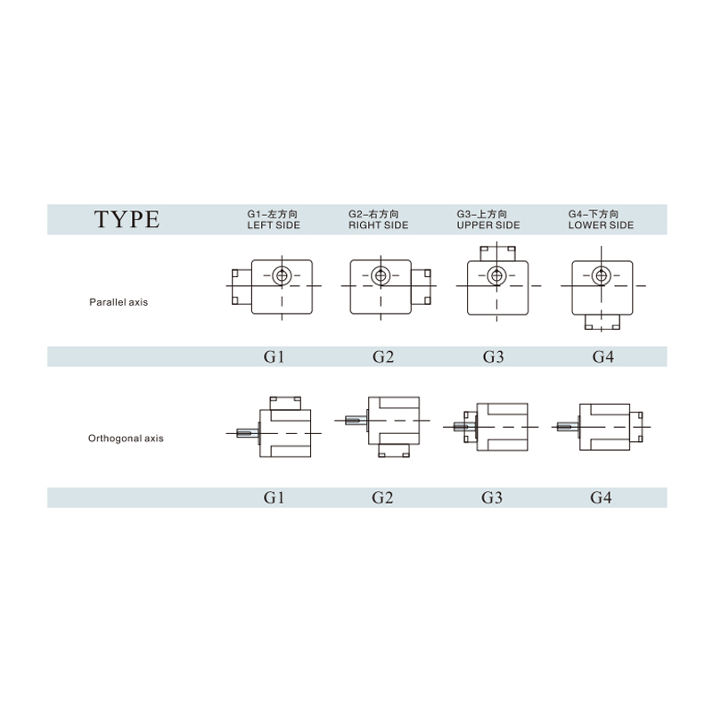
Cat:Motor Controller & Accessories
Junction Box Orientation Selected offers flexible installation options to match different equipment layouts and wiring requirements. Available in four...
See Details -
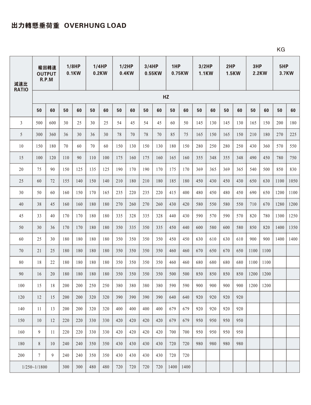
Cat:CH
The CH, CV Overhung Load component is designed to provide reliable support and load management for transmission systems, helping improve the stability...
See Details
Looking For Business Opportunity?
Request for a call today

Zhanpeng Machinery sincerely cooperates with people at home and
abroad to create common development and achieve win-win
results!
Contact Us
-
 sales@razhanpeng.com
-
 +86 13335770176
-
 No. 2807, Huaming Road, Ruian City, Wenzhou City,Zhejiang Province,China
Quick Links
Message


Copyright 2024 Ruian Zhanpeng Machinery Co., Ltd.
Gear Motor Factory


Contact Us