


 English
 中文简体
中文简体 عربى
عربى
Ways to Reduce Noise with Compact Brushless Motors
A motor that sits far from the user can be forgiven for making some sound. One built into a handheld device, a kitchen appliance, or a piece of office equipment cannot. Distance amplifies nothing; proximity reveals everything. As products shrink, the motor moves closer to the ear, and whatever noise it produces becomes part of the user's experience.
Brushless designs changed the baseline. Removing brushes eliminated a mechanical contact point and the sparking that comes with it, which lowered the acoustic signature compared with older alternatives. That improvement did not make the motor silent. Other sources remained, and in compact designs those sources sit closer to the surface, with less material between them and the surrounding air.
The question worth working through is what actually generates sound in a brushless motor, and which measures address which source. Noise is rarely the product of one thing. It comes from electrical switching, mechanical rotation, airflow, and structural response, and each behaves differently. A gear motor factory, as part of the supply chain, deals with these factors during assembly and testing, though the final acoustic result depends on how the motor is integrated into the product.
What Makes a Compact Brushless Motor Quieter Than Alternatives?
Several characteristics give brushless designs a quieter starting point.
- No brush contact: mechanical friction between brushes and commutator disappears, along with the associated wear and sound
- Electronic commutation: current switching happens through control circuitry rather than physical contact, removing sparking noise
- Balanced rotor construction: mass distribution can be controlled more precisely, which reduces vibration at speed
- Lower mechanical losses: fewer contacting parts translate to less frictional noise during operation
- Compact integration: the motor can be mounted with attention to isolation from the start, rather than adapted after the fact
These advantages establish a favorable baseline rather than a quiet result. The remaining noise sources — electromagnetic, mechanical, aerodynamic, and structural — still require attention. In compact designs, the margin for error is smaller because there is less material to absorb or deflect sound, and because the motor sits closer to the surfaces that radiate it.
What Sources of Noise Remain in a Brushless Design?
Sound from a brushless motor comes from several places at once, and they interact.
Electromagnetic noise originates in the switching process. Current changes direction rapidly, and the resulting forces act on the windings and stator. Torque ripple — small variations in output as the rotor turns — contributes to this category. Switching frequency itself can fall within the audible range, which turns the drive electronics into a noise source.
Mechanical noise comes from bearings, rotor balance, and shaft alignment. A bearing that is not seated properly, a rotor that carries slight imbalance, or a shaft that sits off‑center will all produce vibration that radiates as sound.
Aerodynamic noise appears when internal airflow moves through cooling paths or around rotating parts. In compact motors, the space available for air movement is limited, which can increase velocity and therefore noise.
Structural resonance occurs when vibration from the motor matches a natural frequency of the housing or mounting surface. At that point, the structure amplifies what the motor produces. This is why a motor that runs quietly on a test bench can become noticeably louder once installed.
Load‑induced noise comes from whatever the motor drives. Gear meshing, belt contact, and driven components all contribute. In compact assemblies, the gearbox often sits close to the motor, which means its noise adds directly to the total.
Installation‑related noise depends on mounting rigidity and contact surfaces. A motor bolted directly to a thin panel transmits vibration into that panel, which then acts as a speaker. Isolation measures address this, though they are easier to include during design than to add later.
| Noise Source | Typical Cause | Corresponding Measure |
|---|---|---|
| Electromagnetic | Switching frequency, torque ripple | Field‑oriented control, sine wave drive, PWM adjustment |
| Mechanical | Bearings, rotor balance, shaft alignment | Precision bearings, balancing, alignment tolerances |
| Aerodynamic | Internal airflow velocity | Cooling path design, reduced turbulence |
| Structural | Housing and panel resonance | Damping, isolation mounts, stiffer housings |
| Load‑induced | Gear meshing, driven components | Tooth profile, lubrication, backlash settings |
| Installation | Mounting rigidity, contact surfaces | Elastomeric isolators, flexible couplings |
How Do Advanced Control Methods Lower Commutation Noise?
A meaningful share of noise in a brushless motor comes from how current is delivered to the windings. Control methods target that process directly.
Field‑oriented control manages current in a way that keeps torque output smooth as the rotor turns. Reducing torque ripple reduces the vibration that accompanies it, which in turn lowers the sound radiated from the motor and its mounting. The effect is most noticeable at low speeds, where ripple is proportionally larger.
Sine wave drive replaces the abrupt current transitions of trapezoidal switching with gradual ones. The result is a smoother electrical waveform and a correspondingly smoother mechanical response. The difference is audible in applications where the motor runs at moderate speeds for extended periods.
PWM frequency adjustment moves the switching frequency above the range where human hearing is sensitive. Above that point, the switching still occurs, but it no longer registers as a tone. This approach addresses one specific source rather than the overall noise profile.
Dead‑time compensation corrects distortion that arises when the control circuitry switches between phases. Without compensation, the current waveform deviates from its intended shape, and that deviation contributes to acoustic noise. Correcting it improves waveform quality and reduces the associated sound.
Ramp control during start and stop addresses a different moment. Abrupt acceleration or deceleration produces a transient that can be louder than steady‑state operation. Gradual transitions avoid that spike.
These methods carry trade‑offs. Higher switching frequencies can increase losses in the drive circuitry. Smoothing torque may reduce peak output slightly. The appropriate balance depends on what the application values, and in many cases the acoustic improvement justifies the cost.
How Do Mechanical and Structural Choices Reduce Vibration?
Electrical measures can only go so far. What remains after the drive is refined comes down to physical construction.
Precision bearings sit at the center of mechanical noise reduction. A bearing that runs true, with the right preload and clean seating, produces less vibration than one that wobbles or sits slightly off‑axis. Ball bearings and hybrid ceramic types offer different trade‑offs — ceramic elements resist wear and run with less friction, though they cost more and behave differently under shock loads.
Slot and pole combinations determine how the magnetic field interacts with the stator as the rotor turns. Certain combinations produce less cogging — the tendency of the rotor to snap between positions rather than rotate smoothly. Selecting a combination that distributes magnetic forces evenly reduces the vibration that cogging generates.
Skewed stator slots take a different approach to the same problem. By angling the slots rather than running them straight, the magnetic interaction spreads across a wider area. Harmonic distortion drops, and the torque ripple that contributes to noise diminishes. The trade‑off is a slight reduction in output for a given size.
Vibration dampers address the path rather than the source. Elastomeric isolators placed between the motor flange and the mounting frame absorb vibration before it reaches the surrounding structure. This is where a motor that runs quietly on a bench can become loud in a product — the bench does not resonate, but a thin housing panel does. Isolation breaks that transmission path.
Rotor balancing and shaft alignment round out the mechanical picture. Imbalance produces a rotating force that grows with speed. Misalignment places uneven load on bearings and couplings. Both are corrected through tolerances and assembly practices rather than through add‑on treatments.
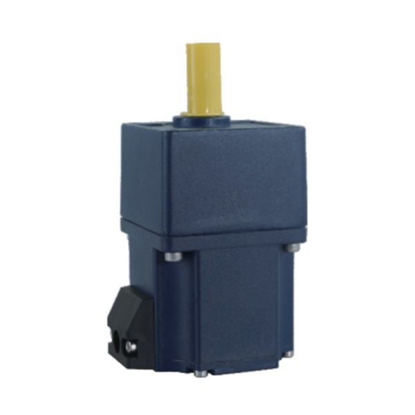
What Role Does the Gearbox Play in Overall Noise?
In many compact assemblies, the motor and gearbox operate as a single unit, and the gearbox contributes its own acoustic signature.
Gear tooth profile shapes how teeth contact each other during rotation. A profile that promotes gradual engagement produces less impact noise than one that engages abruptly. The difference shows up as a whine or rattle that varies with load and speed.
Lubricant choice and fill level affect both wear and sound. A suitable lubricant cushions contact between teeth and reduces friction. Too little lubricant allows metal‑to‑metal contact; too much can increase resistance and churning noise. The right amount depends on the gear type and operating conditions.
Housing material determines how much gear noise reaches the surrounding air. Metal housings transmit sound efficiently, while some polymer housings absorb more of it. The choice involves structural requirements alongside acoustic ones.
Backlash settings influence rattle, particularly when the load reverses direction. A small amount of clearance is necessary for smooth operation, but excess clearance allows teeth to knock against each other. Setting backlash within an appropriate range keeps that noise controlled without causing binding.
A gear motor factory typically evaluates these factors during assembly and testing, since gear noise is difficult to predict from drawings alone. Matching gear ratio to the intended operating speed range also matters — a ratio that places the motor in a quiet range but the gears in a noisy one does not solve the overall problem.
Which Application‑Level Practices Support Quieter Operation?
Once the motor and gearbox are specified, integration decisions determine how much noise reaches the user.
- Operating speeds away from resonance: running the motor at a speed that excites a structural frequency amplifies vibration, even if the motor itself is quiet
- Soft‑start and soft‑stop profiles: gradual transitions avoid the transient noise that accompanies abrupt changes
- Enclosure design: internal surfaces that absorb or redirect sound reduce what escapes
- Vibration isolation between motor and chassis: flexible mounts break the transmission path
- Maintenance practices: bearings and lubricants degrade over time, and quiet operation depends on keeping them in condition
- Testing under representative load: a motor tested without its driven components may show a different noise profile than one tested in the assembled product
Enclosure design deserves attention because it is often treated as a packaging decision rather than an acoustic one. Ribbing, damping material, and internal geometry all influence how sound behaves inside the housing. A rigid panel with large flat surfaces radiates more sound than one with irregular structure or added mass.
Testing conditions matter as much as design choices. Free‑running tests reveal motor noise but miss load‑induced contributions from gears and driven parts. Testing with the full assembly in place, under conditions that resemble actual use, gives a picture closer to what the user experiences.
How Can Noise Reduction Efforts Be Evaluated?
Fixes applied without identifying the dominant source tend to produce disappointing results. Establishing what is actually causing the noise comes before selecting a treatment.
Measurement conditions shape results. Background noise, microphone placement, and mounting method all influence readings. Comparing measurements taken under different conditions can lead to conclusions that do not hold up.
Distinguishing airborne from structure‑borne noise points toward the right category of fix. Airborne noise responds to enclosure treatment and source reduction. Structure‑borne vibration requires isolation or damping at the transmission path. Applying one type of fix to the other type of problem leaves the noise largely unchanged.
Identifying the dominant source comes from testing systematically — changing one variable at a time rather than applying several fixes at once. If switching frequency is the main contributor, mechanical treatment will not help much. If gear meshing dominates, drive adjustments have limited effect.
Cost and complexity vary across approaches. Control parameter changes may require only firmware adjustment. Bearing upgrades or housing redesigns carry tooling and material costs. The appropriate level of investment depends on how much the application values quiet operation.
In some cases, specifying a motor built for lower noise is more practical than treating a noisier unit after the fact. That decision depends on volume, schedule, and how much design flexibility remains. Documenting what changed and what resulted keeps later revisions from repeating work that has already been done.
How Does Quiet Operation Emerge as a System Outcome?
Quiet operation does not come from a single fix. It emerges from decisions made across electrical, mechanical, and structural layers, each addressing a different source.
Control methods reduce commutation noise and smooth torque output. Bearing quality, rotor balance, and slot design address mechanical vibration. Gearbox specification shapes the noise that accompanies power transmission. Housing design and mounting isolation determine how much of that vibration reaches the surrounding air as sound.
A Compact Brushless Motor provides a favorable starting point by removing brush contact and allowing precise rotor construction. What happens after that depends on how the motor is driven, what it is connected to, and how it is mounted.
Treating noise as a design parameter rather than an afterthought gives the best chance of a quiet result. The measures that work are known and accessible. The challenge lies in applying them in the right combination for the specific product, and in testing under conditions that reflect actual use rather than ideal ones.
Related Products
-
-
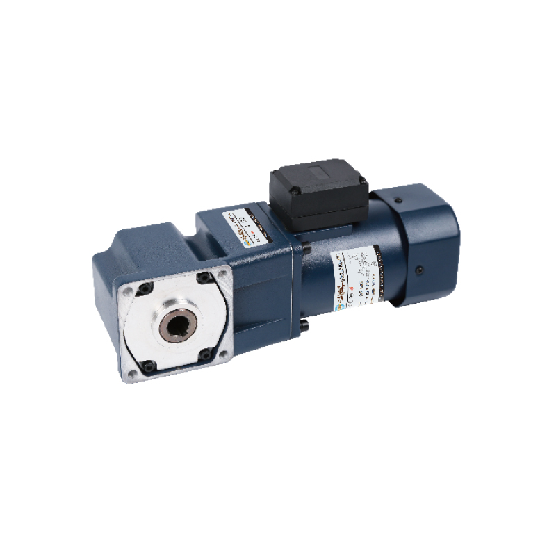
Cat:Right-Angle
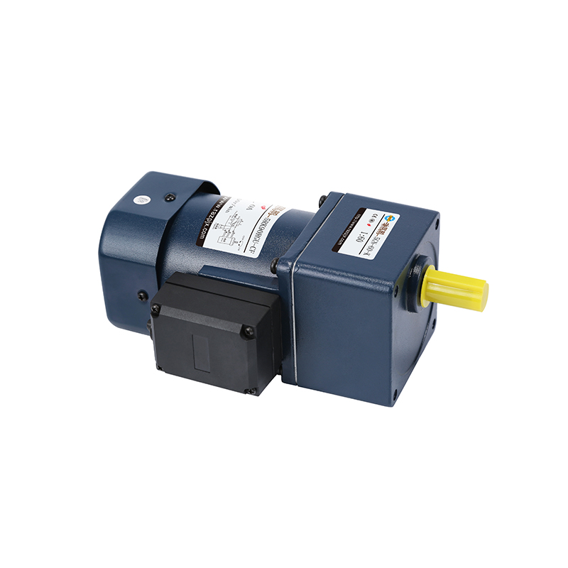
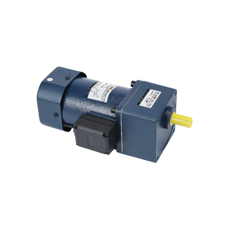
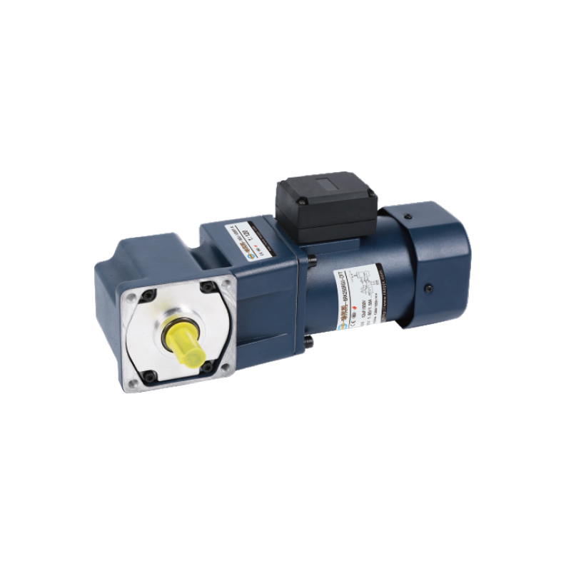
Electric Reduction Motor is designed for stable torque output and controlled low speed operation. This AC Gear Motor Low Rpm provides efficient power ...
See Details -
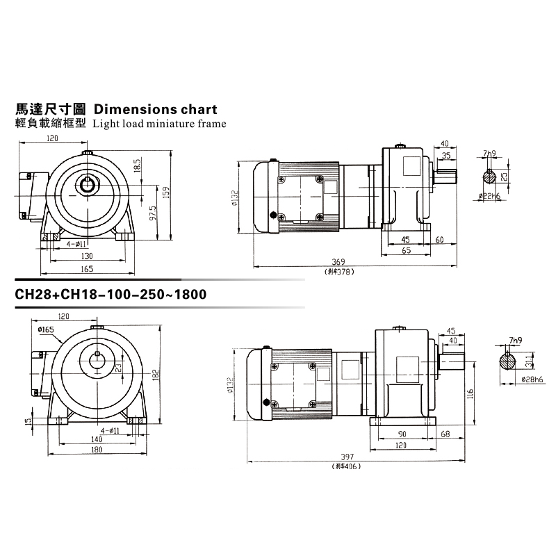
Cat:CH
This CH, CV Dimensions Chart showcases a premium Gear Reduced Electric Motor series engineered for light-load, miniature frame applications. The chart...
See Details
Looking For Business Opportunity?
Request for a call today

Zhanpeng Machinery sincerely cooperates with people at home and
abroad to create common development and achieve win-win
results!
Contact Us
-
 sales@razhanpeng.com
-
 +86 13335770176
-
 No. 2807, Huaming Road, Ruian City, Wenzhou City,Zhejiang Province,China
Quick Links
Message


Copyright 2024 Ruian Zhanpeng Machinery Co., Ltd.
Gear Motor Factory


Contact Us