


 English
 中文简体
中文简体 عربى
عربى
What Feedback Devices Work With an Industrial DC Gear Motor
An Industrial DC Gear Motor running without feedback operates blind. The controller sends power to the motor and assumes the motor does what it is told. If the load changes, the motor responds by slowing down. If the voltage dips, the motor responds the same way. The controller has no way of knowing any of this is happening.
Feedback gives the controller eyes on the motor. A feedback device mounted to the motor measures what is actually happening and sends that information back to the controller. The controller compares what it commanded against what it measured and adjusts the motor output to close the gap.
Some applications need feedback more than others. A motor driving a conveyor at a constant feed rate needs to hold speed. A positioning table that must stop at exact locations needs to know where it is. A winding machine that must maintain consistent tension needs to adjust for changing spool diameters. Each of these tasks becomes difficult without feedback.
What Types of Feedback Devices Are Commonly Used
Tachometers measure rotational speed by producing a voltage that rises and falls with motor velocity. Encoders convert shaft rotation into digital pulses that represent movement and direction. Resolvers use electromagnetic coupling to determine shaft angle without contact.
The choice among these comes down to what the application requires. Speed control alone may need only a tachometer. Positioning and precise speed control often call for an encoder. Harsh environments where optical devices struggle may point toward a resolver.
A few points about each device type:
- Tachometers: simple, reliable, provide speed information only
- Incremental encoders: provide relative position and speed data
- Absolute encoders: retain position after power loss
- Resolvers: withstand vibration and temperature extremes
How Does Tachometer Feedback Work in a DC Gear Motor
A tachometer mounts directly on the motor shaft, usually on the rear extension. Inside the tachometer, a coil rotates in a magnetic field. The faster the shaft turns, the higher the voltage generated. A motor running at top speed produces a certain voltage. A motor running at half speed produces roughly half that voltage.
The controller reads that voltage and uses it to adjust the motor drive. If the load increases and the motor slows down, the tachometer voltage drops. The controller detects the drop and increases power to the motor. The motor speeds back up to the target.
The voltage output range of a tachometer matters for compatibility with the controller. Some tachometers produce output in the range of millivolts per revolution, while others produce higher voltages. Matching the tachometer to the controller ensures the feedback signal is usable.
What Role Do Encoders Play in DC Motor Control
Incremental encoders produce a stream of pulses as the motor shaft turns. The controller counts these pulses and uses the count to determine how far the shaft has rotated. The rate of pulses indicates speed. The direction of rotation can be determined by comparing two pulse channels.
Absolute encoders go further. Each shaft position corresponds to a unique digital code. The code does not change when power is removed. When power returns, the encoder reports the current position without needing to move the motor to a reference point.
Optical encoders sense movement using light passing through a disk with slots. Magnetic encoders use changes in magnetic fields to detect position. Optical encoders offer high resolution but can be affected by dust or moisture. Magnetic encoders handle contaminants better and often suit industrial environments where cleanliness varies.
| Feedback Device | Information Provided | Environmental Tolerance | Typical Applications |
|---|---|---|---|
| Tachometer | Speed only | Good | Speed regulation |
| Incremental encoder | Speed and relative position | Moderate | General motion control |
| Absolute encoder | Speed and absolute position | Moderate | Precise positioning |
| Resolver | Speed and absolute position | High | Harsh environments |
| Hall sensors | Commutation, limited speed | Good | Cost-sensitive applications |
When Is Resolver Feedback the Right Choice
Resolver feedback handles conditions that cause other devices to fail. No optical components, no sensitive electronics, no moving parts beyond the rotor itself. The device relies on electromagnetic coupling between a primary winding and two secondary windings. As the shaft rotates, the amplitude of the signals from the secondary windings changes with the shaft angle.
The resolver provides absolute position information. The controller reads the signals from the secondary windings and calculates the exact shaft angle. The information does not require a reference point or a homing routine. The resolver reports position from the moment it powers up.
The durability of resolvers comes from their construction. No glass disks to break. No light sources to fail. No dust or moisture to block optical paths. The sealed housing protects the windings from contaminants. Resolvers survive in applications where encoders would fail within months.
Common applications for resolvers include heavy equipment, mining machinery, and servo systems that run in dirty or wet conditions. Any application with vibration that would shake an optical encoder loose points toward resolver feedback.
Can Hall Effect Sensors Provide Useful Feedback
Hall sensors offer a cost-effective alternative to more expensive feedback devices. The sensors detect changes in magnetic fields and produce a switching output. Three sensors spaced around a brushless DC motor provide commutation signals that tell the controller when to switch current to each winding.
Hall sensors also provide speed information. The frequency of the switching signals corresponds to motor speed. The controller can use that frequency to estimate how fast the motor is turning. The speed information lacks the resolution of an encoder but works for many applications.
The limitations of Hall sensors for position control deserve attention. A typical Hall sensor setup provides six discrete positions per electrical revolution. The resolution is coarse. For precision positioning applications, an encoder or resolver offers a better solution.
What Factors Determine Which Feedback Device to Choose
The feedback device should match the application's requirements. A simple speed control application does not need an absolute encoder. A precision positioning application likely does.
Environmental conditions restrict the available options. A clean, temperature-controlled environment opens up the choices. A dirty, hot, or vibrating environment narrows the field.
A few factors that guide the decision:
- The required accuracy of speed or position control
- The operating environment
- The system complexity and cost constraints
- The compatibility of the feedback device with the controller
How Does a Custom DC Gear Motor Accommodate Different Feedback Types
Motor design features affect how feedback devices get mounted. A rear shaft extension provides a location for an encoder or tachometer to attach. The mounting surface should be machined to provide a stable reference for the feedback device.
Some motors come with a second shaft extension on the rear of the motor. The extension allows a separate feedback device to be coupled to the motor without interfering with the gearbox. The separate coupling isolates the feedback device from axial loads from the gearbox.
Encoder mounting on the motor rear offers a common approach for closed-loop control. The encoder sits behind the motor, away from the gearbox. The arrangement protects the encoder from gearbox vibration and positions it where it can be accessed for maintenance.
Involving a supplier early in the design process helps ensure that the motor has the features needed to support the chosen feedback. A supplier that offers a Custom DC Gear Motor can incorporate features into the design that would be difficult to add later.
| Consideration | Tachometer | Encoder | Resolver | Hall Sensors |
|---|---|---|---|---|
| Speed control | Good | Good | Good | Fair |
| Position control | Not suitable | Good | Good | Poor |
| Environmental tolerance | Good | Fair | Excellent | Good |
| Cost | Moderate | Moderate | Higher | Low |
| System complexity | Low | Moderate | Higher | Low |
The choice of feedback device shapes how the motor responds in the application. A motor with tachometer feedback holds speed well but does not provide position information. One with encoder feedback offers both speed and position control. A resolver-equipped motor withstands environments that would disable other devices. Hall sensors keep costs low for applications that do not require precise control. The selection should reflect what the application actually needs. An expensive feedback device does not add value if the application does not require its capabilities. A low-cost device that does not meet the requirements creates problems that show up in operation. Matching the feedback device to the motor and the application supports reliable performance over the life of the system.
Related Products
-
-
Cat:Right-Angle
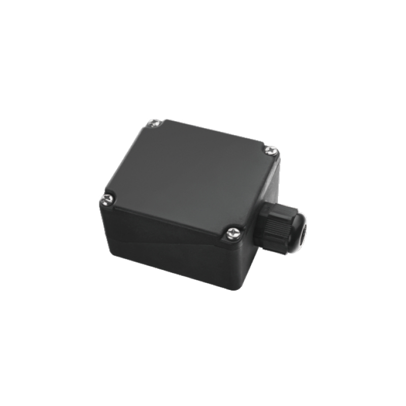
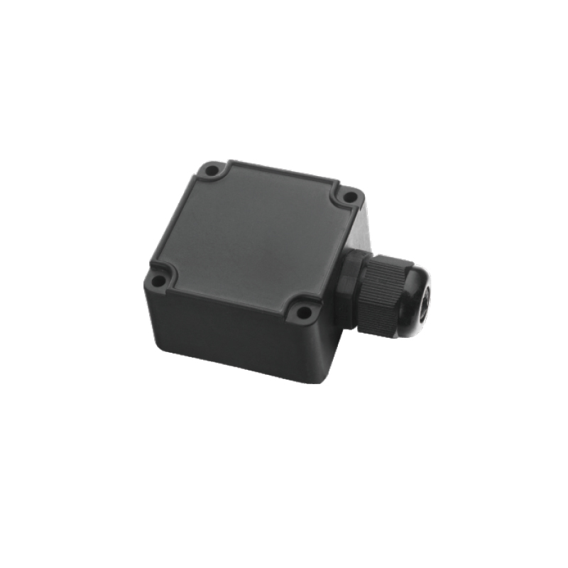
The SX Type Junction Box is designed for safe and reliable electrical connection and cable management in motor and industrial equipment systems. Featu...
See Details -
Cat:CH
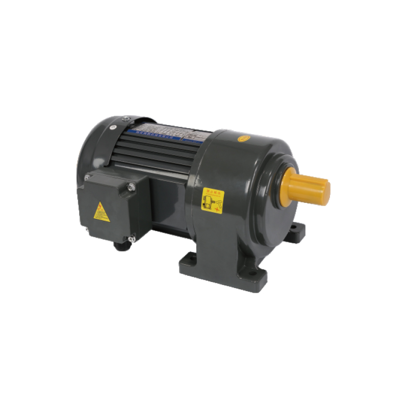
Small AC Gearmotors are designed for compact power transmission with stable torque output and efficient performance. These Fractional HP Gearmotors ar...
See Details
Looking For Business Opportunity?
Request for a call today

Zhanpeng Machinery sincerely cooperates with people at home and
abroad to create common development and achieve win-win
results!
Contact Us
-
 sales@razhanpeng.com
-
 +86 13335770176
-
 No. 2807, Huaming Road, Ruian City, Wenzhou City,Zhejiang Province,China
Quick Links
Message


Copyright 2024 Ruian Zhanpeng Machinery Co., Ltd.
Gear Motor Factory


Contact Us