

 English
 中文简体
中文简体 عربى
عربىCat:Right-Angle
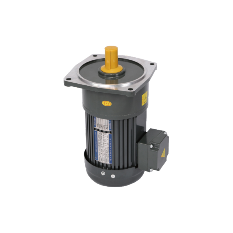
The 90mm 60W VT Reduction Motor is designed for compact equipment that needs a bit more power while keeping a small installation size.It handles autom...
See DetailsIn many machines used for lifting, moving, or positioning, motion is not only about rotation. A system also needs to stop at the right point and stay there without drifting. An AC Brake Gear Motor is built around this idea. It combines three parts in one structure: a motor for driving force, a gearbox for adjusting speed and torque, and a brake unit for holding or stopping motion.
In real use, power enters the motor and creates rotation. That rotation passes through the gearbox before reaching the output shaft. The gearbox slows down speed and increases torque at the same time. A conveyor belt, for example, does not need fast spinning at the output side, it needs controlled movement that can carry weight steadily.
When power is removed or a stop signal is triggered, the brake engages. It locks the shaft so the system does not continue moving from inertia. In everyday equipment, this matters in small ways. A lifted platform staying in place. A rotating arm stopping exactly where it should. A positioning device not slipping after shutdown.
In compact assemblies, Small AC Gearmotors are often used in devices where space is limited. Packaging lines, compact lifting tables, or light transport units usually rely on this kind of structure. The smaller size does not change the need for control, only the installation space.
Mechanical load is often misunderstood as a single fixed value. In real systems, it changes during movement. A motor may face light resistance at the start, then heavier load when material is fully engaged, then a different condition again during stopping.
In daily equipment use, load usually appears in patterns:
A common example can be seen in a small lifting table in workshops. When empty, movement feels light. When tools or materials are placed on it, resistance changes. The motor and brake must handle both conditions without uneven motion.
Rotating parts connected to the motor also matter. A wheel, roller, or drum can keep moving after power is cut. That leftover motion is called inertia in practice. The brake has to handle that energy and bring everything to rest without overshoot.
Load matching is often checked in real installation rather than only in drawings, since surrounding structure changes how force is distributed.
Braking in an AC Brake Gear Motor is closely related to how safe and predictable a machine behaves during stopping. In many mechanical systems, stopping is not a simple pause. It is a controlled transition from movement to rest.
When braking engages, the system must absorb motion energy. In a conveyor line, this prevents materials from sliding forward after stop. In a lifting device, it prevents downward drift after power loss. In positioning equipment, it keeps alignment from shifting.
In repeated use, braking creates heat inside the unit. That heat comes from friction during stopping. Over time, stable heat behavior helps maintain consistent response. Uneven braking often shows up as small jolts during stop cycles or slight position drift after shutdown.
Braking situations in real work usually appear in three moments:
Each situation places a different type of force on the brake. Holding load is often more demanding than stopping motion, since force is continuous rather than brief.
Gear ratio decides how fast output moves compared to motor rotation. It also changes how much force is available at the output shaft. In mechanical systems, this balance affects how smooth and controlled movement feels.
A simple way to observe gear behavior is through everyday equipment. A small conveyor carrying light items may use faster output with lower force demand. A lifting mechanism carrying heavier weight needs slower motion with stronger torque support.
| Gear Behavior | Real Movement Character | Typical Situation |
|---|---|---|
| Higher reduction | Slow, steady rotation | Lifting or holding loads |
| Medium reduction | Balanced motion | General transport systems |
| Lower reduction | Faster rotation | Light mechanical movement |
When gear ratio is not aligned with load type, movement may feel uneven during start or stop. In some cases, the brake has to compensate for mismatch, which increases mechanical stress over time.
In Small AC Gearmotors, space limitation often makes gear selection even more sensitive. Compact structure leaves less room for correction once installed.
Where a motor is installed often shapes how long it stays stable in real use. Even when a system is designed correctly, surrounding conditions slowly affect performance over time.
Temperature changes inside industrial spaces can influence internal components. Continuous warmth may affect insulation layers. Cooler environments may reduce heat stress, though moisture can become more noticeable in enclosed areas.
Dust is another factor often seen in workshops or production lines. Fine particles can enter ventilation gaps and gradually affect gear movement or braking consistency.
Space also matters in a practical way. Some machines leave little room around the motor body. Airflow becomes restricted, which changes how heat leaves the system. That is why Small AC Gearmotors are often used where installation space is tight and airflow is limited.
Vibration from nearby machines also plays a role. Continuous vibration slowly affects mounting stability, which may lead to slight changes in alignment over long use periods.
Common real-world conditions include:
Each condition does not act alone. They combine over time and shape how the motor behaves after long cycles of operation.
Once an AC Brake Gear Motor is placed into a real system, electrical behavior starts to shape how stable everything feels during movement. In practical settings, power supply rarely stays perfectly steady. Small shifts in voltage or current often show up during starting, running, and stopping stages.
At start-up, current demand rises quickly. The motor tries to overcome load resistance, and that moment decides how smooth the first movement feels. When supply is stable, rotation begins in a controlled way. When supply fluctuates, the start can feel slightly uneven, especially in systems carrying weight or connected to gear reduction units.
Brake timing is tied closely to electrical signals. When power is cut, the brake does not react in isolation. It follows the signal path from the control circuit. Any delay or inconsistency in that signal can reflect directly in stopping position. In some machines, that shows up as a small drift after shutdown, enough to matter in positioning tasks.
In daily installation work, a few electrical points are usually checked:
Electrical conditions and mechanical movement stay linked throughout operation. One side shifts, the other responds.
Heat is always present when the motor runs. It builds slowly from coil activity inside the motor and from friction inside the brake unit. Over time, that heat spreads through the housing and reaches surrounding parts.
In short operation cycles, temperature rise may not feel obvious. After longer use, the difference becomes easier to notice. The housing feels warmer, braking response may change slightly, and movement sound can shift in tone.
Brake units react strongly to temperature. Repeated stopping creates friction, and friction turns into heat. When cycles happen too frequently, heat does not fully leave the system before the next stop begins. That accumulation affects consistency.
In real use, heat influence often appears in small ways:
Airflow around the motor plays a quiet role here. In open installations, heat escapes more easily. In tight spaces, especially around compact machinery, heat tends to stay longer inside the housing.
Material behavior also matters. Some internal parts expand slightly when temperature rises. Even small expansion changes can affect spacing between components, which slowly influences alignment between gear and brake sections.
Small AC Gearmotors are often chosen when space is limited, yet controlled movement is still required. Their reduced size helps with installation, though it also makes the system more sensitive to small changes in load and alignment.
In compact layouts, airflow is often restricted. Heat does not leave as quickly, so temperature balance becomes more noticeable during long running periods. That affects both gear section and brake section over time.
Mounting precision also becomes more important. A slight shift in position can influence shaft alignment more easily than in larger systems. In short travel mechanisms, even small deviation can be felt in motion accuracy.
Typical uses include:
In these situations, braking accuracy is often more noticeable. A small overshoot or drift becomes easier to observe because the movement range is limited. That is why stable response matters more than raw output.
Long-term durability in an AC Brake Gear Motor is not only about material strength. It comes from how evenly internal force spreads during repeated use. Every rotation cycle applies pressure to gears, shafts, and brake surfaces.
When shaft alignment stays steady, wear spreads more evenly across contact points. When alignment shifts slightly, pressure concentrates in certain areas. Over time, that difference begins to affect smoothness of motion.
Gear contact quality also plays a role. Smooth engagement reduces small impact points during rotation. Repeated impact, even if small, slowly changes surface condition inside the gearbox.
Brake components experience repeated friction during every stop cycle. That friction is normal in operation, though uneven pressure or heat buildup can affect how consistent stopping feels over time.
In practical use, durability often depends on a few quiet factors:
These elements do not show immediate changes. They develop slowly through daily use, especially in systems that run through many cycles without long breaks.
After installation, an AC Brake Gear Motor becomes part of a larger mechanical chain. Its behavior is influenced by everything connected to it, not only its internal structure.
Transmission parts such as couplings, belts, or linkages affect how motion reaches the working end of the system. Any small slack or misalignment in those parts can change how smooth rotation feels during operation.
Control systems also shape performance. Sensors and switches decide when movement starts and when braking is triggered. When timing is not fully aligned, stopping position may shift slightly between cycles.
Maintenance access often becomes a practical issue in compact systems. When space is limited, cleaning or inspection may not happen frequently. Over time, dust buildup or small wear changes may go unnoticed, which slowly affects performance stability.
Integration behavior usually depends on:
Once installed, the motor does not operate alone. It reacts to the system around it, and small changes in any connected part can gradually influence overall movement behavior.

The 90mm 60W VT Reduction Motor is designed for compact equipment that needs a bit more power while keeping a small installation size.It handles autom...
See Details
The SX Type Junction Box is designed for safe and reliable electrical connection and cable management in motor and industrial equipment systems. Featu...
See Details
Junction Box Orientation Selected offers flexible installation options to match different equipment layouts and wiring requirements. Available in four...
See Details
The Mirco and Special Electronic product series is designed for compact electronic equipment and precision transmission applications requiring stable ...
See Details
The CH, CV Output Torque provides essential performance data for evaluating transmission capacity and equipment matching. It specifies torque output v...
See Details
The CH, CV Overhung Load component is designed to provide reliable support and load management for transmission systems, helping improve the stability...
See Details
The CH, CV Output Shaft Diameter Table provides standardized dimensional data for selecting compatible transmission components and mechanical assembli...
See Details
The CH, CV Ratio / Gear Stage Table provides standardized transmission ratio and gear stage information to support equipment selection and system desi...
See DetailsRequest for a call today
![]()
 sales@razhanpeng.com
 +86 13335770176
 No. 2807, Huaming Road, Ruian City, Wenzhou City,Zhejiang Province,China


Copyright 2024 Ruian Zhanpeng Machinery Co., Ltd.
Gear Motor Factory


Contact Us